Views: 0 Author: Site Editor Publish Time: 2026-07-03 Origin: Site


Selecting a Cold Room Air Cooler represents a fundamental thermodynamic decision that dictates facility energy consumption and product integrity. Facility managers constantly face the operational tension between maximizing heat transfer surface area and managing frost accumulation. Incorrect fin spacing inevitably leads to system icing, restricted airflow, compressor strain, and costly product spoilage. You cannot treat this as a generic hardware purchase. The physical geometry of the coil block determines how well the system handles moisture loads under real-world conditions. This guide provides a technical evaluation framework for specifying equipment based on temperature zones, moisture loads, and long-term operational efficiency. We will break down the engineering principles behind coil design and explain how to match your refrigeration hardware to the specific demands of your storage environment.
Fins act as extended heat transfer surfaces attached to the refrigerant tubes in a cold storage evaporator. They increase the area available for thermal exchange with the ambient air. Bare copper or aluminum tubes simply do not possess enough surface area to cool large volumes of air efficiently. By pressing thin metal plates along the length of the tubes, manufacturers exponentially increase the contact zone. As warm room air passes over these cold metal surfaces, heat transfers from the air into the refrigerant boiling inside the tubes. The physical distance between these plates determines how much air can pass through the block and how easily moisture can bridge the gap.
In field applications, the fin material also plays a role. Aluminum is the industry standard due to its excellent thermal conductivity and low weight. Some aggressive environments require epoxy-coated fins to prevent corrosion. Regardless of the material, the primary function remains the same: maximize heat absorption while allowing sufficient airflow. When you alter the distance between these plates, you fundamentally change the aerodynamic and thermodynamic profile of the unit.
Engineering an air cooler requires balancing capacity and airflow. More fins mean more surface area, which yields higher theoretical capacity. However, tightly packed fins create a higher air pressure drop. This resistance requires more fan power to push air through the coil block. If the fans cannot overcome the static pressure, air velocity drops. Low air velocity leads to poor temperature distribution inside the room and reduces the overall heat transfer coefficient of the coil.
We measure this resistance in Pascals. A coil with 4mm spacing might present a pressure drop of 50 Pascals, while a 10mm coil under the same airflow might only present 20 Pascals. When frost begins to form, the gap narrows further. A 4mm gap quickly becomes a 2mm gap, doubling or tripling the air resistance. This forces the fan motors to work harder, increasing amp draw and generating excess heat that the refrigeration system must then remove. It is a compounding failure loop that starts with specifying the wrong geometry.
Tube specifications, including diameter and wall thickness, interact with fin spacing to influence boundary layer development. The arrangement of tubes, whether staggered or in-line, also affects the overall heat transfer coefficients. Staggered tube arrangements force the air to change direction as it moves through the block. This creates turbulence, which breaks up the thermal boundary layer and improves heat transfer. However, this turbulence also increases air resistance and provides more impact points for moisture to freeze.
In-line tube arrangements offer lower air resistance and are easier to clean, but they generally provide lower heat transfer rates. When you combine a staggered tube pattern with tight fin spacing, you create a highly efficient but highly vulnerable coil. The air must navigate a complex, narrow maze. Any moisture in the air will rapidly condense and freeze on the leading edges of the tubes and fins. Understanding this interaction helps engineers select the right coil block for specific humidity conditions.
Frost formation and condensation occur when ambient air reaches the dew point upon contact with the evaporator coils. Air holds water vapor. Warm air holds more vapor than cold air. When the room air hits the freezing metal surfaces, it rapidly cools and releases its moisture. If the coil surface is above freezing, this moisture forms condensation and drips into the drain pan. If the coil surface is below freezing, the moisture undergoes deposition, turning directly into ice crystals.
Frost acts as an insulator. It has a much lower thermal conductivity than aluminum or copper. A layer of frost just 2mm thick can degrade thermal performance by over 30%. Furthermore, frost physically blocks airflow. As the ice crystals grow outward from the metal surfaces, they bridge the gap between the fins. Once the gap is bridged, air can no longer pass through that section of the coil. The system loses capacity, the room temperature rises, and the compressor runs continuously in a futile attempt to reach the setpoint.
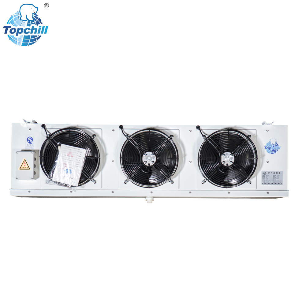
Typical spacing ranges from 4mm to 6mm. These coolers are used in processing rooms, loading docks, and fresh produce storage. In these environments, the coil surface temperature often remains above freezing, or it dips slightly below freezing but has ample time to clear during the compressor off-cycle. Frost formation is minimal. Narrow spacing is optimal here to maximize heat transfer efficiency and keep the physical footprint of the unit small.
However, you must specify adequate spacing to handle condensate film thickness. Even without ice, water forms a film on the fins. If the fins are too close together, capillary action can hold the water between the plates, restricting airflow. A 4mm pitch is generally safe for standard produce storage, but high-humidity processing areas might require 6mm to ensure rapid drainage of condensate.
| Application Type | Room Temperature | Recommended Spacing | Primary Moisture State |
|---|---|---|---|
| Loading Docks | +5°C to +10°C | 4mm - 5mm | Liquid Condensate |
| Fresh Produce | +1°C to +4°C | 4mm - 6mm | Heavy Condensate / Light Frost |
| Meat Processing | +2°C to +7°C | 6mm | High Humidity Condensate |
Typical spacing ranges from 6mm to 8mm. Applications include chilled goods, dairy, and short-term meat storage. Frosting is a constant operational reality in these environments. The coil surface is always below freezing during operation. Moisture from the product and from door openings will accumulate as ice. This spacing provides a balance, allowing sufficient time between required defrost cycles while maintaining adequate cooling capacity.
In a medium-temperature room, a 6mm pitch usually allows for a 4 to 6-hour run time before a defrost cycle is necessary. If you were to install a 4mm coil in this room, you might need to defrost every 2 hours. Frequent defrosting introduces heat into the room, which the system must then remove, wasting significant energy. The 6mm to 8mm range ensures the coil can hold a reasonable amount of frost without choking the airflow.
Typical spacing ranges from 6mm to 12mm, extending up to 20mm depending on moisture load. These units are essential for frozen food storage and deep freeze facilities. High frost resistance is mandatory. Wider spacing prevents rapid ice bridging between fins, ensuring the low temperature air cooler maintains airflow over extended operational shifts.
In a standard holding freezer where products enter already frozen and doors remain mostly closed, a 7mm or 8mm pitch is often sufficient. The moisture load is relatively low. However, in active freezers with frequent forklift traffic bringing in humid ambient air, 10mm or 12mm spacing becomes necessary. The wider gap acts as a larger reservoir for frost accumulation. It allows the refrigeration system to run for 8 to 12 hours between defrosts, stabilizing room temperatures and protecting product quality.
Typical spacing ranges from 12mm to 20mm, or variable fin spacing may be used. These coolers are deployed in shock freezing, blast chillers, and high-moisture freezing applications like hot meat carcasses. Extreme moisture release requires maximum frost tolerance. When you put hot, wet product into a blast freezer, the moisture flashes off rapidly and hits the evaporator coils.
Wide spacing prevents the evaporator from choking within hours of operation. A blast freezer cycle might last 24 to 48 hours. You cannot interrupt this cycle for a defrost without compromising the freezing process and product safety. Therefore, the coil must be able to hold massive amounts of ice while still allowing high-velocity air to pass through. A 16mm or 20mm pitch provides the necessary physical volume to store this ice until the freezing cycle is complete and a full defrost can be initiated.
Decreasing the distance between fins increases the total kW cooling capacity of a specific physical unit size. A compact unit with 4mm spacing might offer 50kW of cooling, while a unit of the exact same dimensions with 10mm spacing might only offer 30kW. This presents a tempting proposition for buyers looking to save space and money.
However, specifying a smaller unit with tight fins that meets the theoretical cooling load can fail in real-world, high-humidity conditions. This capacity trap leads to rapid frosting and system inefficiency. The 50kW capacity only exists when the coil is perfectly clean. Within two hours of operation in a humid environment, frost will block the 4mm gaps. The capacity will plummet to 15kW, the room temperature will spike, and the compressor will run continuously. The 10mm unit, while having a lower initial capacity, will maintain 25kW of cooling for 10 hours because it resists airflow blockage.
There is a direct relationship between air cooler fin spacing and defrosting intervals. Hot gas defrosting and electric defrosting perform differently based on fin spacing. Tight spacing can trap moisture during the defrost cycle. When the heaters turn on, the ice melts into water. In a tightly packed coil, surface tension can hold water droplets between the fins. When the refrigeration cycle resumes, these droplets instantly refreeze into solid ice blocks, permanently degrading capacity until a manual washdown is performed.
Defrosting incurs a massive energy penalty. You are actively heating a room that you just spent money to cool. Electric heaters draw significant amperage. Hot gas defrosting uses compressor energy. Furthermore, all the heat introduced into the coil block and the surrounding air must be removed once the cooling cycle restarts. By selecting wider spacing, you reduce the number of defrost cycles per day from six down to three or two. This drastically cuts energy consumption and reduces thermal shock to the stored products.
Tight fin spacing increases static pressure across the coil. Ice buildup exacerbates this pressure drop, leading to reduced air throw and uneven room temperatures. Axial fans are designed to move large volumes of air at relatively low static pressures. When frost chokes a tight coil, the static pressure spikes beyond the fan's performance curve.
This increased resistance causes premature fan motor failure. The motor draws more current trying to maintain RPM against the blockage. The windings overheat, and the bearings suffer uneven loads due to turbulent airflow. Replacing fan motors in a sub-zero environment is labor-intensive and expensive. Proper spacing ensures the fans operate within their designed parameters, extending equipment lifespan and ensuring cold air reaches the furthest corners of the storage room.
Relying solely on room temperature while ignoring the moisture emitted by the product or infiltration from frequent door openings is a major risk factor. Unpackaged vegetables release significantly more moisture than sealed cardboard boxes. A room held at -20°C storing sealed frozen goods has a completely different thermodynamic profile than a -20°C room where forklift doors open every ten minutes.
Require a comprehensive psychrometric analysis and moisture load calculation before finalizing the specification. You must account for the latent heat load. Every time a door opens, warm, humid air rushes in. This moisture immediately seeks the coldest surface in the room: the evaporator coil. If you specify a 6mm pitch based purely on the -20°C setpoint, but ignore the high infiltration rate, the system will fail. Field engineers must evaluate the operational workflow of the facility, not just the static blueprints.
Modern evaporator designs feature wider spacing on the air inlet side and narrower spacing on the outlet side. For example, the first three rows of tubes might have a 12mm pitch, while the remaining rows have a 6mm pitch. This captures bulk frost at the entry point where the air is most humid, while maintaining high heat transfer efficiency at the rear where the air is drier.
While highly effective in challenging environments, this technology comes at a higher initial capital cost. Manufacturing variable pitch coils requires specialized tooling. However, for blast freezers or high-traffic cold rooms, the operational benefits far outweigh the upfront premium. It provides the frost holding capacity of a wide-pitch coil with the thermal performance of a tight-pitch coil. Facility managers should evaluate this option when dealing with extreme latent loads.
Narrow fins are inherently more difficult to clean and sanitize, posing compliance risks in food-grade facilities. Over time, dust, airborne particles, and biological matter accumulate on the wet coil surfaces. In meat processing or agricultural storage, this buildup can harbor bacteria and mold. Cleaning a 4mm coil block requires high-pressure chemical foam and extensive manual labor.
Factor in the labor costs of manual coil cleaning and the necessity of specialized cleaning agents for tightly packed fin blocks. If the maintenance team cannot easily wash debris through the coil, the unit will suffer permanent capacity loss. Wider spacing, such as 8mm or 10mm, allows cleaning solutions to penetrate the block fully and wash away contaminants. This ensures long-term hygiene compliance and maintains baseline thermodynamic performance.
Evaluate product respiration rates, packaging types, and entering temperature differentials. Align the product profile with the necessary frost resistance threshold to ensure the selected cooler performs optimally under actual storage conditions. Fresh fruits and vegetables actively respire, releasing heat and water vapor. Meat carcasses lose weight through evaporation during the chilling process. All of this moisture ends up on your evaporator.
If you are storing sealed, pre-frozen goods, the product moisture load is zero. You only need to calculate infiltration from doors and panels. If you are chilling open vats of liquid or unpackaged produce, the product moisture load is massive. Build a matrix of your stored goods, their entering temperatures, and their packaging types. Use this data to dictate the physical geometry of your refrigeration equipment.
Reference relevant ASHRAE, AHRI, or local refrigeration standards regarding evaporator performance. Ensure the selected unit meets food safety compliance requirements for your specific application. Regulatory bodies often dictate specific temperature tolerances for perishable goods. If your coil frosts over and the room temperature spikes by 3 degrees, you may violate health codes and be forced to discard inventory.
Furthermore, energy efficiency regulations are becoming stricter globally. Systems that rely on excessive defrost cycles to compensate for poor coil geometry will fail modern energy audits. Specify equipment that has been tested and rated under frosted conditions, not just dry laboratory conditions. Demand performance curves from the manufacturer showing capacity degradation over a standard 8-hour frosting cycle.
There is no universal best fin spacing. Optimal performance requires matching the physical geometry of the air cooler to the specific thermodynamic realities of the cold room. Reject quotes that specify narrow fin spacing for low-temperature or high-moisture applications simply to offer a lower upfront price. The operational costs of continuous defrosting and compressor strain will quickly erase any initial savings.
A: If spacing is too small, rapid ice bridging occurs between the fins. This blocks airflow, drastically reducing cooling capacity and forcing the system into continuous, energy-wasting defrost cycles. The compressor runs constantly, leading to premature mechanical failure and unstable room temperatures.
A: Wider fin spacing accommodates more frost buildup before airflow is restricted. This extends the time between required defrosts, reducing energy waste and maintaining more stable room temperatures. Fewer defrost cycles mean less heat is introduced into the refrigerated space.
A: The standard range is typically 6mm to 12mm. However, environments with high moisture loads, frequent door openings, or blast freezing applications may require spacing up to 20mm to prevent rapid icing and maintain adequate airflow.
A: Using 4mm spacing in a -18°C room is strongly advised against. It will lead to inevitable operational failure, rapid frosting, blocked airflow, and potential compressor damage due to constant strain. The unit will require constant defrosting to function.
A: Variable fin spacing uses a staggered approach, with wider spacing at the air inlet to catch heavy frost and narrower spacing at the outlet to maximize heat transfer efficiency. This balances high frost tolerance with compact physical dimensions.


