Views: 0 Author: Site Editor Publish Time: 2026-09-15 Origin: Site


Refrigeration failure in continuous-process industries carries severe operational consequences. Food processing plants, chemical manufacturing facilities, and cold storage warehouses rely on uninterrupted thermal management to protect product integrity. Standard commercial refrigeration components degrade rapidly under 24/7 maximum-load conditions. This continuous strain leads to thermal bottlenecks, excessive energy consumption, and catastrophic compressor failure.
To prevent these failures, facilities must specify a purpose-built Condenser designed strictly for continuous industrial heat rejection. Standard units simply cannot handle the relentless thermal cycling. The evaluation process for upgrading or installing new equipment must carefully balance thermal capacity, environmental constraints, and lifecycle maintenance requirements. You need equipment that guarantees a reliable phase change under the most extreme ambient conditions.
Capacity vs. Climate: Continuous load handling requires sizing the condenser based on peak summer ambient conditions and the available heat sink, not just average operational loads.
Phase Change Efficiency: The primary function of the condenser is forcing a reliable phase change from high-pressure vapor to liquid; continuous loads require optimized subcooling to prevent system failure.
Material Integrity: True heavy-duty units utilize thicker tube walls, specialized fin designs, and corrosion-resistant coatings to survive constant thermal cycling and harsh environments.
System Synergy: The choice between air-cooled, water-cooled, or evaporative systems dictates the facility's total water and energy footprint.
Maintenance Accessibility: Continuous operation demands designs that allow for cleaning and component replacement without requiring full system shutdowns.
The vapor-compression cycle relies on four core components: the compressor, the condenser, the expansion valve, and the evaporator. In continuous-process environments, the condenser frequently becomes the system's primary thermal bottleneck. Compressors generate massive amounts of heat while pressurizing refrigerant vapor. The condenser must receive this high-pressure, high-temperature vapor and efficiently transfer that heat to a designated heat sink. This heat sink is typically ambient air or water.
The physics of this phase change are absolute. The condenser must remove both sensible heat to lower the vapor temperature and latent heat to force the vapor to condense into a liquid. Continuous operational loads prevent the refrigeration system from cycling off. The equipment receives no recovery periods. It must reject heat constantly while maintaining a strict temperature differential, known as Delta-T, with the surrounding heat sink.
When the Delta-T shrinks during extreme weather, heat transfer efficiency drops. The vapor fails to fully condense. This forces the compressor to work harder, increasing discharge temperatures and risking mechanical breakdown. A properly specified unit prevents this by maintaining adequate surface area and airflow to guarantee the phase change regardless of the internal load. Field engineers often see standard units fail during peak summer months because the coil surface area simply cannot reject the accumulated heat of compression fast enough.
Continuous operation means the metal components remain in a state of thermal expansion. The fan motors run without stopping, stressing bearings and belts. The internal refrigerant velocities remain high, scouring the inside of the copper or steel tubes. Only equipment designed for these specific stresses will survive a 24/7 duty cycle.
Many industrial facilities utilize waste heat to drive absorption refrigeration cycles rather than traditional vapor-compression systems. These systems replace mechanical compressors with thermal generators and absorbers. However, the heat rejection requirements remain just as demanding. A heavy duty heat exchanger is required to reject heat from both the condenser and the absorber components. The thermal load on the cooling infrastructure in an absorption system is often higher than in a mechanical system, demanding robust heat rejection equipment.
In these setups, the cooling water loop must handle the combined heat rejection of the entire thermodynamic cycle. If the heat exchanger fouls or loses capacity, the absorption chiller loses its ability to generate the necessary refrigeration effect, leading to immediate process temperature deviations.
A true heavy duty condenser is engineered differently than standard commercial units. The structural and thermodynamic differences are distinct. Standard units use thin-gauge metals and tightly packed fins to save space and reduce weight. Heavy-duty units prioritize longevity and continuous performance over physical footprint.
Component | Standard Commercial Specification | Heavy Duty Industrial Specification |
|---|---|---|
Tube Wall Thickness | 0.012" to 0.016" (Prone to vibration leaks) | 0.025" to 0.035"+ (Resists high pressure and vibration) |
Fin Spacing | 10 to 14 Fins Per Inch (FPI) (Clogs easily) | 4 to 8 FPI (Allows debris to pass, easier to clean) |
Casing Material | Thin-gauge G60 Galvanized Steel or Aluminum | Heavy-gauge G90 Galvanized or 304/316 Stainless Steel |
Fan Motors | Standard AC motors, light-duty bearings | TEFC or EC motors, severe-duty bearings, VFD compatible |
Structural Frame | Self-supporting coil block | Independent structural steel frame isolating the coil |
Industrial units utilize heavier gauge galvanized steel or stainless steel casings to prevent flexing under continuous fan vibration. Reinforced motor mounts prevent structural fatigue from 24/7 fan operation. Industrial-grade cast aluminum or composite fan blades resist deformation and provide consistent airflow under high static pressure. Tube diameters are larger, and wall thicknesses are increased to withstand high internal refrigerant pressures. Fin spacing is optimized for low fouling rather than maximum compactness.
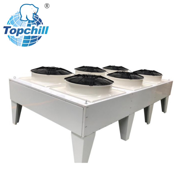
A high capacity air cooled condenser transfers heat directly to an ambient air heat sink. It uses powerful fans to draw air across finned refrigerant coils. The phase change is forced entirely through the sensible cooling capacity of the ambient air.
The primary advantage of this mechanism is zero water consumption. Facilities avoid the complex chemical treatments, blowdown regulations, and plumbing infrastructure associated with water-based cooling. Maintenance is generally limited to mechanical fan inspections and periodic coil cleaning. However, air-cooled units require a significantly larger physical footprint to achieve the necessary heat transfer surface area.
They also suffer capacity drops during extreme high ambient temperatures. When summer temperatures peak, the air-to-refrigerant Delta-T shrinks. Facilities must size these units for the absolute highest historical ambient temperature to prevent compressor failure. These units are best for facilities with strict water usage restrictions, cooler geographic climates, or remote installations where water piping is impractical. Engineers must account for the massive air volumes required, ensuring the installation location has adequate clearance to prevent hot air recirculation.
Evaporative systems utilize a combination of forced air and a continuous water spray over the condensing coils. This mechanism leverages the latent heat of vaporization. As the water evaporates off the hot coils, it absorbs massive amounts of heat from the refrigerant inside the tubes. Evaporating one pound of water absorbs roughly 1,000 BTUs of heat, making this process exceptionally powerful.
This process is highly efficient. Evaporative units maintain much lower condensing temperatures than air-cooled units, which drastically reduces compressor energy consumption. They also require a smaller physical footprint than air-cooled alternatives of the same capacity. The major drawback is the absolute necessity of continuous water treatment. Operators must rigorously manage mineral scaling, biological growth, and corrosion.
Evaporative systems are best for large-scale industrial plants. They are the industry standard for industrial ammonia refrigeration systems where minimizing compressor energy usage is the highest priority. The water basin requires regular cleaning, and the spray nozzles must be inspected to ensure even water distribution over the entire coil block. Dry spots on an evaporative coil lead to rapid scale formation and localized heat transfer failure.
Water-cooled systems use shell-and-tube or plate heat exchangers located inside the plant room. These units are connected to a separate, external cooling tower loop. The water acts as a highly stable heat sink, absorbing heat from the refrigerant and carrying it outside to the cooling tower.
This mechanism provides extremely stable condensing temperatures regardless of ambient air conditions. The internal heat exchangers are highly compact, saving valuable plant room floor space. However, this system requires managing a secondary cooling water loop, dedicated pumps, and extensive cooling tower maintenance.
Water-cooled systems are best for high-rise industrial facilities, marine applications, or manufacturing plants that already possess centralized cooling tower infrastructure for other processes. The shell-and-tube design allows for mechanical cleaning of the water tubes by removing the end bells and punching the tubes with specialized brushes. This maintains optimal heat transfer efficiency over decades of continuous use.
Condenser Type | Primary Heat Sink | Water Consumption | Footprint Requirement | Best Application Environment |
|---|---|---|---|---|
Air-Cooled | Ambient Air | Zero | Very Large | Water-restricted areas, cooler climates |
Evaporative | Air & Water (Vaporization) | High | Medium | Large ammonia plants, high energy-efficiency needs |
Water-Cooled | Cooling Tower Water Loop | Moderate to High | Small (Indoor) | Facilities with existing cooling towers, marine use |
Evaluating continuous load handling starts with calculating the Total Heat of Rejection (THR). The THR is not just the net cooling load of the facility. It must also include the heat of compression added by the refrigeration compressors themselves. Under continuous operation, the compressors run at maximum capacity, generating peak heat loads that the condenser must dissipate instantly.
You must specify equipment based on worst-case design temperatures for your specific geographic location. For air-cooled units, this means sizing based on the peak summer dry-bulb temperature. For evaporative and water-cooled units, you must size based on the peak summer wet-bulb temperature. Failing to account for these worst-case ambient variables guarantees that the heat sink will become unviable during summer months, leading to high head pressure trips and facility downtime.
Engineers use historical weather data, typically the ASHRAE 0.4% or 1% design conditions, to establish these baselines. However, for continuous-process facilities where downtime is unacceptable, sizing based on the absolute historical maximum temperature provides a necessary safety margin.
Continuous-duty compressors require a steady supply of pure liquid refrigerant. If vapor bubbles, known as flash gas, reach the expansion valve, system efficiency plummets and the compressor can suffer mechanical damage. Heavy-duty condensers are engineered with dedicated subcooling circuits.
These circuits route the condensed liquid refrigerant through an additional pass of coils at the bottom of the unit. This extra cooling step lowers the liquid temperature below its saturation point. Proper subcooling ensures the refrigerant is 100% liquid before it leaves the condenser, protecting the entire refrigeration cycle under continuous load conditions. Subcooling also increases the net refrigeration effect of the system, providing more cooling capacity per pound of refrigerant circulated.
Material selection dictates the lifecycle of the equipment. Continuous thermal cycling places immense stress on coil tubes and fins. You must evaluate copper, aluminum, and stainless steel based on your specific refrigerant and operating environment.
Copper: Excellent heat transfer but incompatible with ammonia refrigerants. Vulnerable to formicary corrosion in certain industrial environments.
Aluminum: Lightweight and highly resistant to ammonia. Often used for fins and microchannel coils.
Stainless Steel: The ultimate choice for harsh industrial environments and heavy ammonia systems. It offers unmatched durability and corrosion resistance, though it has slightly lower thermal conductivity than copper.
Carbon Steel: Traditionally used in large ammonia evaporative units, heavily hot-dip galvanized after fabrication to prevent rust.
Protective coatings are mandatory in corrosive industrial or coastal environments. Specify factory-applied epoxy coatings, electro-finning, or hot-dip galvanizing for the entire coil block. These coatings prevent airborne chemicals or salt spray from degrading the heat transfer surfaces. Field-applied coatings rarely provide the uniform coverage necessary to protect the deep inner rows of a thick coil block.
Maintaining precise head pressure control is critical during fluctuating ambient conditions, even when the internal refrigeration load is continuous. Variable Frequency Drives (VFDs) on condenser fans are essential. VFDs allow the fan motors to ramp up or down smoothly in response to real-time pressure sensors.
This prevents the harsh mechanical wear of rapid on/off fan cycling. Furthermore, evaluate the fan motor types. Electronically Commutated (EC) motors offer superior continuous duty efficiency compared to traditional AC motors. EC motors consume significantly less electricity at partial speeds and generate less internal heat, extending the life of the motor bearings. Proper airflow management also involves ensuring the unit is installed with adequate clearance. Starving the fans of air or allowing hot discharge air to recirculate back into the intakes will destroy the unit's capacity.
Continuous operation accelerates the accumulation of debris and scale. For air-cooled units, the primary risk is airborne debris such as dust, pollen, and industrial particulates. This debris clogs the coil fins, drastically reducing heat transfer efficiency and disrupting the phase change. To mitigate this risk, specify wider fin spacing for dusty environments. Standard commercial fins are too dense for industrial air quality. Implement a strict maintenance schedule utilizing compressed air or specialized coil cleaners to keep the air path clear.
For evaporative and water-cooled units, mineral scale is the primary threat. As water evaporates, it leaves behind calcium and magnesium deposits on the hot tubes. Scale acts as an insulator, destroying thermal conductivity. You must implement automated water treatment systems. These systems monitor water conductivity and automatically trigger blowdown valves to flush concentrated minerals from the basin, replacing them with fresh makeup water. Chemical dosing pumps must inject scale inhibitors and biocides continuously to protect the metal surfaces.
Heavy-duty units carry significant operating weights. This weight increases dramatically when the coils are fully flooded with liquid refrigerant and, in the case of evaporative units, when the water basin is full. Roof-mounted installations present severe structural risks.
You must outline the need for comprehensive structural engineering reviews before installation. The roof structure must support the flooded operating weight, not just the dry shipping weight. Additionally, continuous fan operation generates significant vibration. Implement heavy-duty spring vibration isolators between the condenser frame and the structural steel to prevent transmitting harmonic vibrations into the building envelope. Wind shear is another major factor for large air-cooled units. The structural supports must be engineered to withstand local maximum wind loads, preventing the unit from shifting or overturning during severe weather.
Industrial refrigeration is heavily regulated regarding refrigerant usage. You must ensure strict compatibility between the condenser materials and the chosen refrigerant. Natural refrigerants like Ammonia (NH3) and Carbon Dioxide (CO2) are replacing synthetic low-GWP refrigerants in large facilities due to environmental regulations.
Ammonia is highly corrosive to copper and brass. An ammonia system requires carbon steel, stainless steel, or aluminum tubes. Using copper components in an ammonia system will result in rapid, catastrophic failure. CO2 systems operate at extremely high pressures, requiring specialized heavy-wall stainless steel tubing to handle the transcritical operating pressures safely. The piping design must accommodate these high pressures, utilizing proper relief valves and welded connections to ensure absolute system integrity under continuous load.
Continuous operation demands designs that allow for cleaning and component replacement without requiring full system shutdowns. When evaluating equipment, prioritize units with hinged fan panels, external grease zerks for motor bearings, and easily removable access doors. If a technician has to unbolt fifty fasteners just to inspect a spray nozzle, maintenance will be deferred, leading to premature failure.
Evaporative units should feature large access hatches to the water basin and drift eliminators. Air-cooled units should have cleanout doors between coil slabs if multiple coils are banked together. The easier the equipment is to access, the more likely the maintenance team will perform the necessary preventative tasks.
Continuous operation accelerates wear. Specifying redundancy directly impacts facility uptime. Instead of relying on a single massive coil block, consider dual-circuit coils or installing multiple smaller units. If a fan motor fails or a coil develops a leak on a dual-circuit system, you can isolate the damaged section while the rest of the unit continues to provide partial cooling capacity.
Redundant fan configurations also provide a safety net. If one fan on a six-fan unit fails, the VFDs can ramp up the remaining five fans to compensate, maintaining head pressure until a replacement motor is installed. This level of redundancy is mandatory for continuous-process facilities where a total loss of refrigeration means losing millions of dollars in product.
Initiate a comprehensive facility load calculation that includes both peak cooling loads and total compressor heat of compression.
Conduct a professional water-quality test to determine the exact chemical treatment requirements if considering an evaporative system.
Perform a structural engineering review of your proposed installation location to verify it can support the flooded operating weight of industrial equipment.
Consult with a licensed industrial refrigeration engineer to finalize coil material specifications based on your selected refrigerant and local ambient extremes.
A: Typically 15-25 years. This lifespan is heavily dependent on maintenance. For evaporative units, strict water treatment quality determines longevity. For air-cooled units, consistent coil cleaning frequency prevents premature failure.
A: As ambient air temperature rises, the temperature differential between the air (heat sink) and the refrigerant shrinks. This reduces heat transfer efficiency, impedes the vapor-to-liquid phase change, and forces compressors to work harder.
A: Heavy duty models feature thicker tube walls, wider fin spacing to prevent clogging, industrial-grade fan motors, dedicated subcooling circuits, and materials designed to withstand continuous vibration and thermal stress.
A: Capacity is calculated by determining the Total Heat of Rejection (THR). The THR equals the net cooling load of the facility plus the heat of compression added by the refrigeration compressors.
A: Evaporative condensers are the industry standard for large ammonia systems due to their high efficiency. Stainless steel or aluminum air-cooled units are used where water is restricted. Copper components cannot be used.
A: Continuous loads require daily visual and automated monitoring. Perform monthly mechanical inspections on belts, motors, and water quality. Deep coil cleaning must occur at least bi-annually or quarterly depending on environmental debris.


