Views: 0 Author: Site Editor Publish Time: 2026-07-09 Origin: Site


Sub-zero industrial cooling carries exceptionally high stakes. Temperature fluctuations lead to catastrophic product loss, and equipment failures trigger massive operational downtime. Standard single-compressor systems struggle in these demanding environments. Direct expansion systems routinely fail to manage variable thermal loads effectively, unable to maintain consistent refrigerant flow across large-scale facilities. Facility managers need a robust, specialized solution. The Low-Temperature Barrel Pump parallel screw unit solves these exact problems. It separates liquid delivery from vapor compression, providing unmatched efficiency for heavy-duty industrial applications. This technical evaluation guide breaks down the mechanics, use cases, and implementation trade-offs of this advanced refrigeration technology. You will learn how to size the equipment, mitigate installation risks, and maximize system uptime.
The barrel pump functions as the heart of the liquid delivery network. It supplies liquid refrigerant to evaporators at a constant, reliable pressure. This mechanism forms the foundation of a robust pump circulation system. The pump utilizes a twin-screw positive displacement design. It features a distinct figure-eight shaped barrel housing. Inside this housing, two intermeshing helical rotors operate in tandem. One rotor features a right-hand thread, while the other features a left-hand thread. This opposing geometry traps and moves the fluid axially, preventing vapor lock and eliminating cavitation risks.
The design excels at handling highly volatile fluids. It easily processes low-viscosity refrigerants dropping below 1 cP at sub-zero temperatures. It also manages gaseous mixtures without losing prime. The complete barrel assembly houses several critical components designed for continuous industrial operation. Internal baffling prevents liquid sloshing and vapor entrainment, ensuring only solid liquid enters the pump suction. Precision level sensors monitor the liquid inventory continuously, feeding data back to the central control panel to prevent dry running.
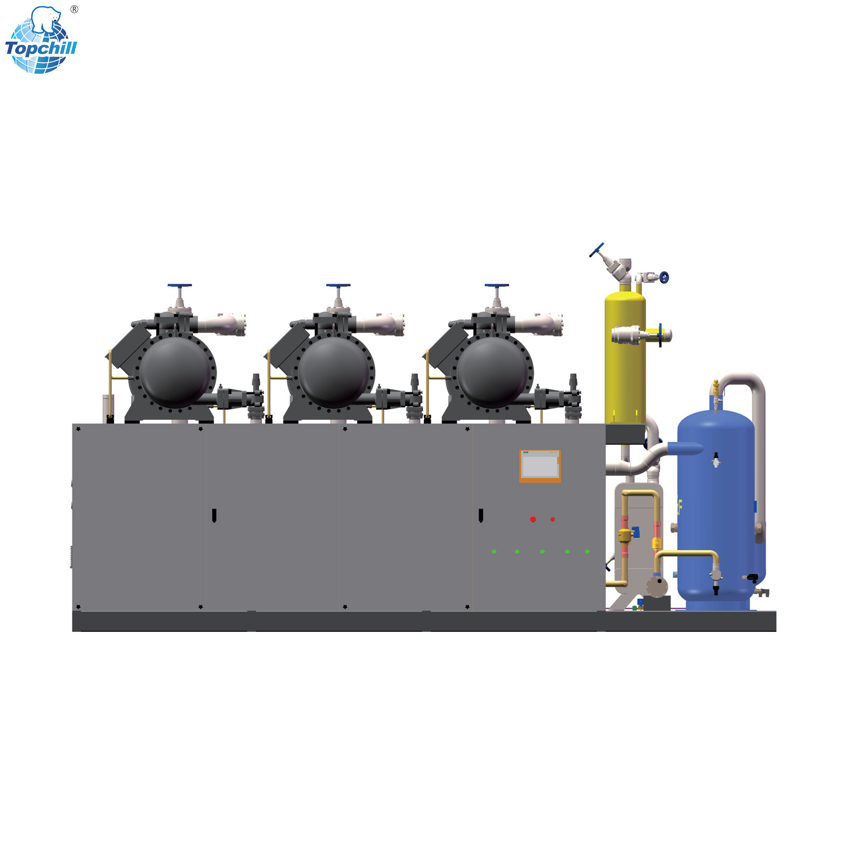
Parallel twin-screw compressors operate on a shared refrigeration circuit. This architecture fundamentally changes how cooling capacity is generated. A standard compressor skid mounts multiple compressors on a single structural frame. These parallel screw compressors discharge into a shared oil separator and draw from a common liquid receiver. The skid features centralized gauge panels for immediate visual diagnostics. Integrated high and low-pressure safety protection systems monitor the entire rack, shutting down individual compressors before catastrophic failure occurs.
Shared oil management is a defining characteristic of parallel configurations. A common discharge header collects hot gas from all active compressors. This centralized approach reduces piping complexity and ensures uniform oil return across the operating compressors. The oil separator utilizes coalescing filters to strip microscopic oil mist from the discharge gas, returning it to a shared reservoir. From there, an active oil distribution system feeds lubrication back to each compressor based on its specific runtime and load.
Refrigerant flow follows a precise, engineered path. Vapor leaves the evaporators and enters the parallel screw unit. The compressors elevate the pressure and temperature. The gas moves through the condenser, becoming a high-pressure liquid. This liquid expands into the low-pressure receiver. The barrel pump refrigeration unit then draws this sub-cooled liquid and drives the fluid out to the evaporators across the facility.
This creates a mechanical overfeed system. The pump delivers more liquid than the evaporators can actually boil off. This overfeed ensures the internal evaporator tubes remain fully wetted. Fully wetted tubes maximize the internal heat exchange coefficient. Heat transfer efficiency increases dramatically compared to starved coils. The excess liquid and generated vapor return to the low-pressure receiver, where the gas is drawn back to the compressors and the liquid is recirculated by the pump.
Cooling demands fluctuate wildly in industrial facilities. Product loading, ambient weather, and shift changes alter the thermal load. Parallel units adapt by staging compressors on and off. The control system matches active compressor capacity to real-time cooling demand. This precise load matching represents a massive efficiency gain. When the facility requires only 40% capacity, the system runs only the necessary compressors at their peak efficiency point.
Compare this to a single large compressor. Large compressors use slide valve unloading to reduce capacity. Running a massive compressor at 30% capacity wastes significant energy. Motor efficiency drops sharply at deep part-load conditions. A parallel rack simply shuts down unneeded compressors. The remaining active compressors run at peak efficiency near full load, drastically reducing the overall electrical draw of the plant.
Standard reciprocating pumps create severe fluid pulsation. This pulsation causes vibration fatigue in rigid pipework, leading to cracked welds and catastrophic refrigerant leaks. The twin-screw mechanism in the barrel pump eliminates this issue. It delivers continuous, pulsation-free flow. This smooth delivery protects the entire piping network from mechanical stress, extending the lifespan of valves, fittings, and evaporator coils.
It proves vital when pumping volatile and low-viscosity fluids. Stable refrigerant flow directly translates to temperature uniformity. Critical applications demand exact temperature control. Pharmaceutical storage facilities require zero temperature deviation to protect sensitive biologicals. Blast freezing operations rely on consistent heat removal to form micro-crystals in food products. Stable flow guarantees these stringent parameters are met consistently, shift after shift.
Equipment failure is inevitable in heavy industry. Parallel systems inherently mitigate this risk. If one compressor requires emergency maintenance, the system does not crash. The remaining compressors ramp up to maintain the baseline load. Facility operations continue without interruption. Maintenance teams can isolate the faulty compressor, perform repairs, and bring it back online without ever shutting down the main cooling process.
This redundancy carries massive financial implications. In many sectors, downtime equals immediate product spoilage. Medicine and vaccine storage cannot tolerate a loss of cooling. Food processing and quick-freezing lines halt entirely if temperatures rise. Chemical manufacturing processes can become unstable or dangerous. Parallel units safeguard these high-value operations through continuous uptime, acting as an insurance policy against catastrophic facility failure.
Selecting the right equipment starts with the primary refrigerant. Industrial plants typically utilize Ammonia (NH3), Carbon Dioxide (CO2), or synthetic low-GWP blends. Each fluid exhibits unique thermodynamic properties. Ammonia offers excellent efficiency but requires steel piping and strict safety protocols. CO2 operates at extreme pressures, demanding heavy-wall piping and specialized valves. Synthetic blends behave differently under deep vacuum and require specific elastomer seals.
Fluid viscosity dictates the internal engineering of the barrel pump. At sub-zero temperatures, liquid viscosity often drops below 1 cP. This ultra-thin fluid can slip past standard pump rotors, reducing volumetric efficiency. Engineers must specify exact machining tolerances for the screw profiles. Material selections for the pump internals must account for thermal contraction. Specialized hardened steel alloys prevent galling and ensure the pump maintains pressure even with highly volatile, low-viscosity refrigerants.
| Refrigerant Type | Operating Pressure | Viscosity at -40°C | Material Requirements |
|---|---|---|---|
| Ammonia (NH3) | Low to Moderate | Very Low (<0.3 cP) | Carbon Steel, Stainless Steel (No Copper) |
| Carbon Dioxide (CO2) | Very High | Low | High-Tensile Steel, Specialized Elastomers |
| Synthetic Blends | Moderate | Moderate | Compatible with Copper and Steel |
Accurate sizing requires calculating the total thermal load. Engineers determine the required tons of refrigeration (TR) or kilowatts (kW) based on product throughput, transmission loads, and infiltration. They must balance this capacity against the physical footprint of the plant room. Space is often a premium in existing facilities, requiring creative layout solutions and compact equipment designs.
Parallel compressors offer distinct space-saving benefits. Mounting multiple compressors on a single frame condenses the footprint. They share a single massive oil separator. They utilize a common receiver and a centralized control panel. This vertical and consolidated integration frees up valuable floor space compared to standalone units. It also simplifies the field piping, as contractors only need to connect to single suction and discharge headers on the skid.
Modern low temperature industrial refrigeration relies on advanced automation. Programmable Logic Controller (PLC) integration is mandatory. The PLC acts as the brain of the parallel rack. It executes the staging logic, monitors safety parameters, and optimizes the pump speed based on system demand. The control system must interface seamlessly with the facility's overarching SCADA network.
The system requires comprehensive telemetry to function safely. Sensors must track suction and discharge pressures continuously. High and low-pressure protections must trigger instant shutdowns during faults. Oil temperature sensors prevent lubrication breakdown. Pump differential pressure switches confirm actual fluid flow. Variable frequency drive (VFD) statuses provide real-time motor speed data. All this data allows operators to trend performance and predict maintenance needs before failures occur.
Pump circulation systems utilize a mechanical overfeed mechanism. Direct expansion (DX) systems rely on dry expansion. In a DX system, the refrigerant boils completely into a gas before leaving the evaporator. This requires a portion of the evaporator coil to act as a superheater. That section does no useful cooling, effectively wasting heat exchange surface area.
DX systems struggle in sprawling cold storage facilities. Uneven refrigerant distribution plagues long pipe runs. Evaporators furthest from the compressors starve for liquid, leading to warm spots in the warehouse. Barrel pumps excel in these exact scenarios. The pump forces liquid uniformly to every evaporator, regardless of distance. Heat transfer remains maximized across the entire facility, ensuring tight temperature control even in the most remote corners of the building.
| System Feature | Low-Temperature Barrel Pump System | Standard Direct Expansion (DX) |
|---|---|---|
| Refrigerant Delivery | Mechanical overfeed via positive displacement pump | Pressure differential and thermostatic expansion valves |
| Evaporator Efficiency | High (fully wetted internal tube surfaces) | Lower (requires superheat zone, dry tubes) |
| Large Facility Distribution | Excellent, uniform flow regardless of distance | Poor, prone to pressure drops and starved coils |
| Load Fluctuation Handling | Superior, parallel staging matches demand exactly | Moderate, relies on single compressor unloading |
| Piping Complexity | Requires return lines and low-pressure receivers | Simpler point-to-point piping |
Facility owners must evaluate the realistic financial trade-offs. A parallel pump system carries a higher upfront capital expenditure. The equipment is heavier, more complex, and requires specialized controls. Installation takes longer and demands highly skilled pipefitters. The initial investment includes the cost of the pump skid, the parallel compressor rack, and the associated low-pressure receiver vessels.
However, the operational expenditure reduction is substantial. Energy savings accumulate rapidly due to precise load matching and fully wetted evaporators. Maintenance frequency decreases because compressors share the run-hour burden. The return on investment timeline typically falls between three to five years. For large-scale operations, the long-term energy savings heavily outweigh the initial premium, making it the financially sound choice for facilities planning to operate for decades.
A parallel screw unit requires specialized maintenance protocols. Technicians must perform regular oil analysis to detect internal wear. Vibration monitoring on the barrel pump identifies bearing degradation early. Laser shaft alignment ensures the motor and pump operate without binding. These tasks require trained personnel and specialized diagnostic equipment.
Despite this complexity, lifecycle longevity improves dramatically. Multiple compressors share the annual run-hour load. A lead-lag control strategy rotates the primary compressor weekly. This prevents any single machine from accumulating excessive wear. A single overworked compressor in a standard system will require a complete overhaul years before a parallel rack needs major service. The distributed workload extends the mechanical life of the entire system.
Oil management dictates the survival of any refrigeration system. Oil logging in the evaporators is the most common failure point in low-temperature applications. At sub-zero temperatures, compressor oil becomes thick and viscous. It resists flowing back up the suction lines, pooling in the evaporator coils and insulating the tubes, which destroys heat transfer efficiency.
Engineers must implement aggressive solutions within the parallel screw unit. Multi-stage oil separators capture 99.9% of the oil before it leaves the skid. Coalescing filters strip microscopic oil mist from the discharge gas. In extreme low-temperature ammonia systems, oil rectifiers actively distill oil from the liquid receiver. These mechanisms ensure proper oil return to the compressor bearings, preventing mechanical failure and maintaining evaporator performance.
Retrofitting a large barrel pump skid into an existing plant room presents logistical hurdles. The physical dimensions of the skid often require removing walls or widening access doors. Rigging the heavy equipment into place demands careful structural planning. Floors must be reinforced to handle the concentrated weight of the receiver vessels and compressor racks.
Electrical infrastructure usually requires a complete upgrade. Existing panels may not support multiple compressor motor starts. VFDs introduce electrical harmonics into the plant grid. Engineers must install harmonic filters and upgrade switchgear. Proper grounding is critical to protect the sensitive PLC components from electrical noise. Failing to address the electrical requirements during the design phase will lead to severe commissioning delays.
The commissioning phase determines the ultimate success of the installation. Contractors must execute rigorous pressure testing using dry nitrogen to ensure zero leaks in the complex piping network. Vacuum dehydration must pull the system down to 500 microns to remove all moisture. Any residual moisture will freeze and destroy the pump rotors or clog expansion valves.
Engineers must verify the PLC staging logic under simulated thermal loads. They force sensor inputs to test high-pressure cutouts and oil failure alarms. The acceptance criteria for handover must be strict. The system must hold setpoint temperatures for 72 hours continuously. Pump differential pressure must remain stable. Compressor staging must operate smoothly without short-cycling. Only after passing these rigorous tests should the system be handed over to the facility operators.
A: These pumps are designed for highly volatile, low-viscosity industrial refrigerants. They handle Ammonia (NH3), Carbon Dioxide (CO2), and various synthetic low-GWP blends at sub-zero temperatures where fluid viscosity drops below 1 cP.
A: Parallel units provide precise load matching by staging compressors on and off. This significantly reduces energy consumption at part-load conditions. It also provides critical redundancy; if one compressor fails, the others keep the facility running.
A: It uses a mechanical overfeed mechanism. The pump delivers more liquid refrigerant than the evaporator can boil off. This ensures the internal tubes remain fully wetted, maximizing the heat transfer coefficient compared to dry expansion systems.
A: Upgrading the electrical infrastructure is usually the largest hurdle. Existing facilities often lack the switchgear capacity for multiple motor starts. Installing variable frequency drives (VFDs) also requires proper harmonic filtering and grounding.
A: The systems utilize multi-stage oil separators and coalescing filters on the compressor discharge. For extreme low temperatures, active oil rectifiers distill trapped oil from the low-pressure receiver and return it to the compressors.
A: No. Unlike reciprocating pumps, the intermeshing helical rotors of a twin-screw pump deliver a continuous, pulsation-free flow. This smooth operation protects rigid pipework from vibration fatigue and mechanical stress.


