Views: 0 Author: Site Editor Publish Time: 2026-07-16 Origin: Site


Inadequate airflow in industrial refrigeration systems introduces severe hidden operational costs, ranging from excessive energy consumption to catastrophic compressor failure. Restricted or insufficient airflow directly compromises heat transfer across the Evaporator coil. This failure leads to system inefficiency, increased mechanical wear, and compromised product quality or facility throughput. Facility managers and technicians must understand how to evaluate whether a system requires routine maintenance, airflow re-balancing, or a complete upgrade to a higher-capacity unit. This guide provides a technical framework to diagnose airflow deficits, understand environmental variables, and make data-driven decisions on system interventions to keep your plant running at peak performance.
Identify mechanical symptoms: Dropping suction pressure, skewed refrigerant measurements, and chronic ice formation at the evaporator coil inlet are primary, measurable indicators of airflow failure.
Account for environmental variables: High-altitude operations reduce air density and degrade nominal tonnage ratings, requiring specific volumetric airflow adjustments to maintain target mass flow rates.
Evaluate engineering trade-offs: Arbitrarily increasing airflow does not linearly increase cooling capacity; high air velocity prevents the coil from dropping to the dew point, limiting dehumidification.
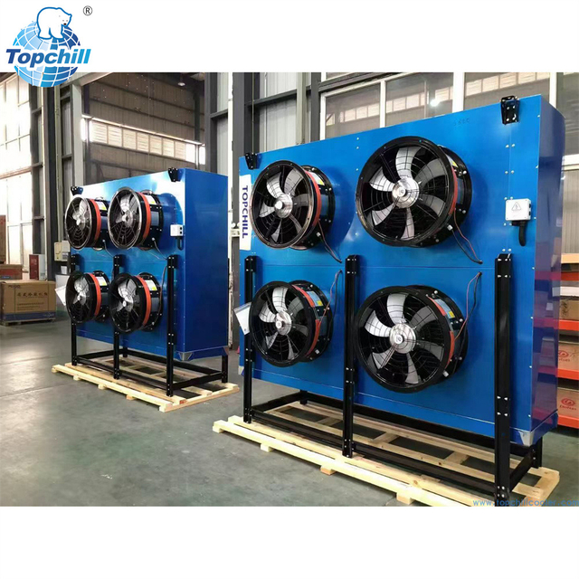
Determine the intervention level: Differentiate between reversible maintenance issues (e.g., fouled blower wheels, restricted inlets) and fundamental specification failures requiring a specialized workshop refrigeration air cooler or high capacity air cooler.
Low airflow across the coil disrupts the fundamental thermodynamic balance of the refrigeration cycle. When the volume of air passing over the fins decreases, the system absorbs less heat from the conditioned space. Because the refrigerant inside the tubes boils at a rate proportional to the heat it absorbs, reduced heat transfer causes the refrigerant to boil off slower. This directly results in a falling suction pressure returning to the compressor. Technicians will notice the saturation temperature dropping below design specifications.
If low suction pressure remains unaddressed, the compressor experiences significant mechanical strain. The most immediate risk is liquid slugging. When refrigerant fails to fully vaporize in the coil due to lack of heat load, liquid droplets travel down the suction line and enter the compressor cylinders. Compressors are designed to pump vapor, not liquid. Slugging causes blown head gaskets, broken valves, and catastrophic internal damage. Additionally, low suction pressure means the returning refrigerant gas is less dense, which fails to adequately cool the compressor motor windings, leading to overheating.
Evaluating pressure drops requires comparing current superheat and subcooling measurements against original manufacturer specifications. A system with restricted airflow typically presents with low suction pressure and low superheat. Establishing baseline diagnostic metrics allows maintenance teams to identify airflow degradation before it triggers a mechanical failure.
Diagnostic Metric | Normal Operation | Restricted Airflow Indication |
|---|---|---|
Suction Pressure | Matches design saturation temp | Significantly lower than design |
Superheat | 8°F to 12°F (typical) | Approaching 0°F (floodback risk) |
Compressor Amp Draw | Within RLA rating | Lower than normal (less mass flow) |
Restricted air causes coil temperatures to drop rapidly. When the coil surface temperature falls below the freezing point of water and below the dew point of the surrounding air, moisture condenses and immediately freezes on the fin surfaces. This process initiates frost accumulation. The coil inlet serves as the primary diagnostic checkpoint. Frost typically accumulates here first due to localized temperature drops and the initial reduction in air velocity as air hits the fin pack.
Ice creates a compounding failure loop. Initial frost acts as a highly effective insulator, preventing heat from reaching the refrigerant. This further drops the coil temperature. Simultaneously, the physical bulk of the ice blocks the gaps between the fins, restricting airflow even more. This accelerates the freezing process until the entire coil becomes a solid block of ice, entirely halting system cooling capacity.
Technicians must differentiate between normal frost loads and abnormal freezing. Normal frost occurs in low-temperature applications and is managed by standard, timed defrost cycles using electric heaters or hot gas. Abnormal freezing happens rapidly between defrost cycles and strongly indicates blower failures, slipping fan belts, or severely clogged air filters.
Inspect the coil face visually for uneven frost distribution.
Measure the air velocity at the return air grille using an anemometer.
Check the defrost timer and termination thermostat for proper operation.
Verify the fan motor amp draw to ensure it is operating at full capacity.
Reduced heat transfer severely impacts Individual Quick Freezing (IQF) applications and blast freezers. These systems rely on high-velocity air to rapidly remove heat from products, freezing them individually before ice crystals can damage cellular structures. When airflow drops, the heat transfer coefficient plummets, extending the time required to bring the product down to the target core temperature.
Insufficient air velocity disrupts the fluidization process in IQF tunnels. Products like berries, peas, or diced meats must be suspended in a high-velocity updraft to freeze separately. Without adequate airflow, the product bed collapses. Items freeze together into large clumps, leading to significant moisture loss, freezer burn, and rejected batches.
The business cost of this degradation is substantial. Extended freezing times reduce overall facility throughput, creating bottlenecks in production schedules. Slower batch times increase energy consumption per pound of product. Furthermore, failing to meet rapid temperature reduction requirements compromises compliance in strict food safety environments, risking bacterial growth and product recalls.
Standard Cubic Feet per Minute (CFM) calculations assume operation at sea level. However, air density decreases as altitude increases. The physical distance between air molecules expands, meaning a cubic foot of air at 5,000 feet contains significantly less mass than a cubic foot at sea level. Refrigeration systems absorb heat based on the mass flow rate of air (pounds of air per hour), not just the volume.
This lower air density degrades the nominal or listed tonnage of a standard commercial refrigeration air cooler. A unit rated for 10 tons of cooling at sea level may only deliver 8.5 tons at a higher elevation because the thinner air carries less heat energy per cubic foot. To compensate, the system must move a larger volume of air to achieve the same mass flow rate.
Calculating the required increase in volumetric airflow involves applying altitude correction factors to the baseline CFM. Facility engineers must specify larger fan motors or adjust blade pitches to increase the CFM proportionally to the drop in air density. Failing to adjust for altitude guarantees chronic underperformance and frequent low-pressure lockouts.
Ambient humidity levels strictly dictate airflow requirements. Sensible heat changes the temperature of the air, while latent heat involves the phase change of moisture (condensation). Environments with high humidity introduce massive latent heat loads. If airflow is too low, the coil temperature drops sharply, causing rapid moisture extraction that quickly turns into severe frost scaling.
Dynamic load balancing is critical in environments like a heavy-duty workshop refrigeration air cooler application. In these spaces, large bay doors frequently open and close, introducing massive volumes of unconditioned, moisture-heavy outside air. The system must have sufficient airflow to handle sudden spikes in latent heat without immediately freezing the coil. Proper airflow management ensures the coil remains above the critical freezing threshold while still managing the sensible temperature pull-down.
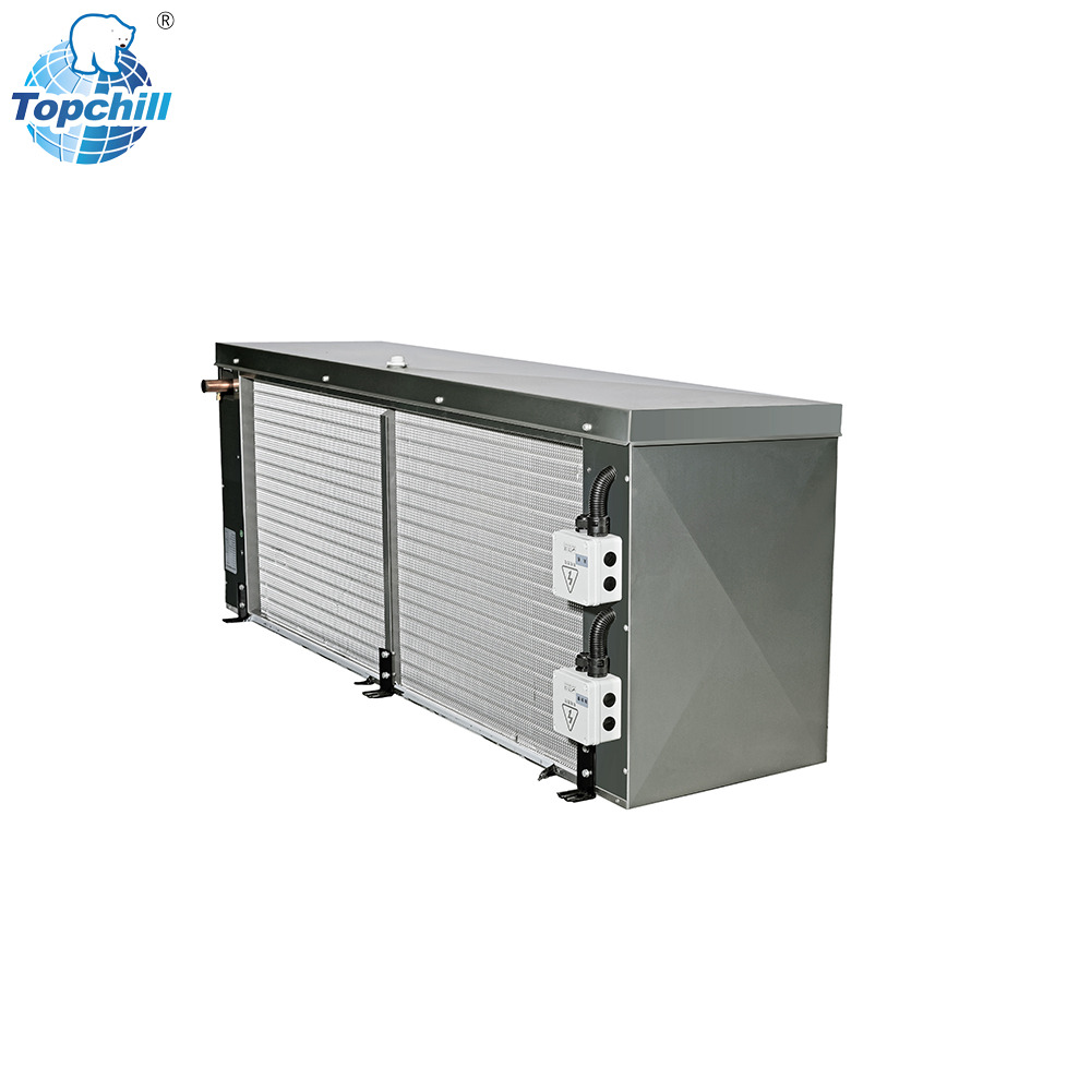
Before considering equipment upgrades, technicians must audit the physical airflow path. This begins with inspecting the coil inlet for debris, plastic wrap, or accumulated dust that physically blocks air entry. Next, verify blower wheel cleanliness; even a thin layer of dirt on fan blades alters their aerodynamic profile, drastically reducing CFM. Technicians should also check belt tension on belt-driven fans to ensure no slippage occurs and inspect motor mounts for vibration that could indicate bearing wear.
Refrigerant measurement analysis helps isolate the root cause. A system with restricted airflow will show low suction pressure and low superheat. Conversely, a system with an actual refrigerant undercharge will show low suction pressure but high superheat. Accurate gauge readings prevent technicians from incorrectly adding refrigerant to a system that simply needs a filter change or coil cleaning.
Establish strict criteria for maintenance effectiveness. Deep cleaning, chemical coil washing, and replacing worn belts should restore the unit to factory-rated airflow. If static pressure readings and anemometer tests confirm airflow remains insufficient after comprehensive maintenance, the system suffers from a fundamental design limitation.
Maintenance cannot overcome facility heat loads that have outgrown the original equipment design. When production volumes increase, or when a facility introduces hotter products into the space, the existing cooling infrastructure hits an operational threshold. At this point, no amount of cleaning will force a small coil to absorb the required heat.
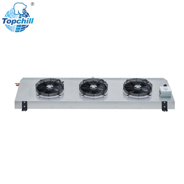
Standard commercial units feature tighter fin spacing and smaller fan motors designed for moderate, predictable loads. In contrast, heavy-duty industrial unit cooler systems are built for demanding, high-throughput environments. They utilize wider fin spacing to resist frost buildup, heavy-gauge casings to withstand industrial wear, and high-static fans capable of pushing air through dense product stacks.
Upgrading to a high capacity air cooler allows engineers to match the specific sensible-to-latent heat ratio of the space. Specialized industrial spaces require robust equipment that can maintain high volumetric airflow without suffering from rapid frost scaling, ensuring continuous operation during peak production shifts.
Increasing airflow is not a universal solution; it presents a direct inverse relationship with moisture removal. Dehumidification relies on the air spending enough time in contact with the cold coil fins to drop below its dew point. When air velocity is too high, the air rushes past the fins too quickly. The coil temperature rises slightly due to the massive volume of relatively warm air, preventing it from dropping sufficiently below the dew point.
This thermodynamic limit suppresses dehumidification. While the space may reach the target sensible temperature, the relative humidity remains uncomfortably or dangerously high. In food processing or pharmaceutical storage, high humidity leads to condensation on walls, floors, and packaging.
Furthermore, excessive air velocity introduces the mechanical risk of moisture carryover. If fans pull air too aggressively, the velocity overcomes the surface tension of the condensation on the fins. The system literally blows water droplets off the coil and directly into the conditioned space. This moisture carryover causes severe mold growth, slippery floors, and direct product contamination.
Upgrading to larger fan motors incurs a massive operational penalty dictated by the Fan Laws (affinity laws). The relationship between airflow and power consumption is cubic. If you want to double the airflow (CFM), the fan motor requires eight times the electrical horsepower. Small increases in air velocity demand disproportionately large increases in energy consumption, driving up utility bills.
Additionally, larger fan motors introduce a parasitic heat load into the refrigerated space. All electrical energy consumed by the fan motor eventually converts to heat. In a sealed cooler or freezer, the refrigeration system must work harder to remove the heat generated by its own fans. This parasitic heat input directly offsets the net cooling gains achieved by the higher airflow, sometimes rendering the upgrade entirely counterproductive.
Upgrading fans or increasing RPM without analyzing the system's total external static pressure (ESP) invites failure. Every component in the airstream—coils, filters, ductwork, and product stacks—creates resistance. If a technician installs a high-speed fan without addressing restrictive ductwork, the static pressure spikes.
Improper fan sizing against high static pressure leads to motor overload and premature failure. It can also cause aerodynamic stall, where the fan blades churn the air without actually moving it forward. In large industrial spaces, incorrect airflow velocity creates dead spots in air distribution. The "throw" (the distance the air travels before slowing down) must be carefully calculated to ensure uniform temperature distribution across the entire room, preventing warm pockets where product spoilage occurs.
Installing a larger unit in an existing footprint presents severe structural, spatial, and electrical realities. Roof structures or ceiling panels must support the increased weight of heavy-duty equipment. Spatial constraints often dictate custom coil geometries to fit between existing piping and structural beams. Electrically, larger motors require upgraded wiring, heavier conduits, and larger breakers.
Mitigation strategies for retrofitting focus on control and infrastructure. Implementing variable frequency drives (VFDs) allows for precise, demand-based airflow control. VFDs let the system ramp up fan speeds during peak loading and slow down during holding periods, saving energy and preventing moisture carryover. Additionally, retrofits must include upgraded drainage systems. A larger coil handling higher latent loads produces significantly more condensate, requiring wider drain pans and heated drain lines to prevent overflow and ice accumulation.
Conduct a comprehensive system audit utilizing anemometers and manifold gauges to measure current CFM, static pressure, and suction metrics before purchasing new equipment.
Perform a deep clean of the existing coil, blower wheel, and filter systems to rule out reversible maintenance issues before committing to capital expenditures.
Calculate the exact sensible and latent heat loads of your facility, accounting for altitude and product throughput, to determine the true required mass flow rate.
Evaluate the electrical infrastructure and structural supports to ensure the facility can handle the increased weight and power draw of high-capacity upgrades.
A: Poor airflow reduces heat transfer, causing suction pressure to drop. This leads to reduced cooling capacity, rapid frost accumulation on the coil, and severe mechanical risks to the compressor, including liquid slugging and motor overheating.
A: High altitude decreases air density. Thinner air absorbs less heat per cubic foot, degrading the unit's nominal cooling tonnage. Systems must move a higher volume of air to maintain the necessary mass flow rate for effective cooling.
A: No. Doubling airflow requires eight times the fan motor power due to fan laws. Excessive velocity also prevents proper dehumidification, causes moisture carryover into the room, and adds parasitic heat from the larger motors.
A: Freezing at the inlet indicates restricted airflow or a localized temperature drop. Common causes include dirty air filters, fouled blower wheels, slipping fan belts, or a failed defrost cycle that allows initial frost to compound into solid ice.
A: Low airflow reduces the heat transfer rate, extending freezing times. In IQF systems, inadequate air velocity fails to suspend the product, causing items to clump together, lose moisture, and suffer from degraded quality and freezer burn.
A: Industrial coolers are built for heavy-duty, high-throughput environments. They feature wider fin spacing to resist rapid frost buildup, high-static fans to push air through dense product loads, and heavier construction to handle extreme latent and sensible heat loads.