Views: 0 Author: Site Editor Publish Time: 2026-07-30 Origin: Site


Commercial refrigeration systems demand exact maintenance to function properly. When you ignore the hardware, you get premature compressor failure, ruined inventory, and massive energy bills. A strict maintenance schedule keeps the system running at peak efficiency. It extends the life of the equipment and prevents emergency service calls. This guide breaks down exactly how to service these systems safely. We cover safety protocols, cleaning methods, electrical testing, and specific checks for different configurations. You will learn how to handle everything from standard setups to specialized enclosures. Proper field execution prevents downtime and keeps cooling loads stable. We rely on these exact procedures in the field to keep equipment running through peak summer loads.
Routine service prevents catastrophic hardware failures. Dust accumulation on coils forces the compressor to work harder. This increases discharge temperatures and degrades internal lubricants. Thermal stress eventually destroys compressor windings. Regular cleaning and inspection stop this chain reaction before it starts. We see neglected systems fail years before their expected lifespan simply due to dirty coils and ignored electrical connections.
Proactive maintenance delivers a measurable return on investment. Clean coils and properly calibrated controls keep the system running at its designed Coefficient of Performance (COP). This efficiency translates to lower daily energy consumption. It delays the need for expensive capital replacements. When a system operates efficiently, it pulls down to temperature faster and cycles off sooner, saving wear and tear on moving parts.
Maintenance scopes vary by equipment design. A standard commercial refrigeration condensing unit shares basic principles with specialized models, but execution differs. You must adapt your approach based on the specific hardware. The core goal remains the same: maximize heat rejection and protect the compressor. Understanding these variations ensures reliable operation across all cooling applications.
Every technician must understand the specific demands of the equipment they service. A basic Condensing Unit requires straightforward coil cleaning and electrical checks. More complex systems demand deeper mechanical knowledge. You cannot treat a fractional horsepower system the same way you treat a massive rack system. The principles of thermodynamics apply universally, but the mechanical execution changes drastically.
Never bypass safety protocols when working with high-voltage industrial equipment. Proper preparation protects the technician and prevents accidental system damage during the service window. We always assume a circuit is live until proven otherwise with a calibrated meter.
Implement strict Lockout/Tagout (LOTO) procedures before touching any components. Isolate the main electrical supply at the disconnect switch. Verify zero voltage across all phases using a multimeter. Do not rely on non-contact voltage testers for this verification. Use a proper meter with leads to check phase-to-phase and phase-to-ground.
Assemble the necessary tools before beginning the inspection. Having the right equipment on hand streamlines the process and ensures accurate diagnostics. Walking back and forth to the truck wastes time and breaks your focus.
EPA-certified manifold gauges with low-loss fittings to minimize refrigerant release.
Electronic refrigerant leak detectors calibrated to the specific refrigerant in use.
Non-acidic foaming coil cleaners designed for microchannel or standard tube-and-fin coils.
Precision fin combs for aluminum coils to restore proper airflow.
Wet/dry vacuum and flexible drain brushes for clearing condensate lines.
Appropriate safety PPE, including insulated gloves, safety glasses, and arc flash protection if required.
Digital multimeter with amp clamp for checking current draw on motors and heaters.
Megohmmeter for testing compressor winding insulation resistance.
Log operational data before shutting the system down. Record suction pressure, discharge pressure, ambient temperature, and compressor current draw. This baseline data helps identify performance deviations once maintenance is complete. You need to know how the system was running before you touched it to prove your maintenance actually improved performance.
Follow a strict sequence when preparing for maintenance. Skipping steps leads to mistakes.
Observe the unit running and listen for abnormal noises.
Record all operating pressures and temperatures.
Measure and record the voltage and amperage of the compressor and fan motors.
Shut down the system at the thermostat or controller.
Disconnect power at the main breaker and apply LOTO devices.
Verify zero voltage at the contactor.
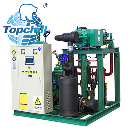
Airflow restriction is the leading cause of high head pressure. Remove all physical obstructions around the housing. Clear away dirt, dust, leaves, and trash. Ensure at least three feet of clearance around the perimeter. We often find boxes or pallets stacked against outdoor units, completely choking off the air supply.
Apply a specialized, non-acidic condenser coil cleaner. Let the foaming action dissolve grease and embedded grime. Rinse the coils thoroughly with low-pressure water. Direct the spray outward from the inside to push debris away from the compressor compartment. Avoid high-pressure washers. They easily crush delicate aluminum fins and force dirt deeper into the coil block.
Inspect the aluminum fins after cleaning. Use a fin comb matching the specific fins-per-inch (FPI) count to carefully straighten any bent sections. This restores unrestricted airflow and maximizes heat rejection. Take your time with this step. Rushing will tear the fins and permanently damage the coil.
Check the fan blades for cracks or missing balance weights. A vibrating fan blade will eventually tear the motor mount apart. Clean the blades with a damp cloth to remove dirt buildup, which can throw off the balance and reduce air volume.
Vibration loosens electrical connections over time. Inspect all terminal blocks, contactors, and relays. Look for signs of corrosion, pitting, or thermal discoloration. Tighten every lug to the manufacturer's specified torque rating. A loose connection creates resistance, which generates heat and eventually melts the terminal.
Test the crankcase heater. Measure its amp draw to confirm operation. A functional heater prevents liquid refrigerant from migrating into the compressor oil during off-cycles. If the heater fails, the compressor will pump liquid on startup, washing the oil out of the bearings and causing mechanical failure.
Verify control calibrations. Test the high and low-pressure safety cutouts. Ensure delay timers function correctly to prevent short-cycling after power interruptions. Check the contactor points for pitting. If the silver coating is burned off, replace the contactor immediately. Do not try to file the points smooth.
Measure the capacitance of all run and start capacitors. A weak capacitor causes the motor to pull higher amps and run hotter. Replace any capacitor that measures outside the +/- 6% tolerance range printed on the label.
Visually inspect all copper joints and valves for oil staining. Oil spots almost always indicate a micro-leak. Follow up visual checks by scanning all connections with an electronic leak detector. Pay special attention to the schrader valves and the king valve packing.
Measure superheat and subcooling to verify the refrigerant charge. Rely on these temperature-pressure calculations rather than connecting gauges unnecessarily. Every time you connect gauges, you vent a small amount of refrigerant. Use wireless probes if possible to minimize loss.
Check the compressor oil sight glass. The level should sit between one-quarter and one-half full during operation. Extract a small oil sample to test for acidity. High acid levels indicate early motor winding breakdown. If the oil tests positive for acid, schedule a system cleanup immediately.
Inspect the filter-drier. Measure the temperature drop across the drier. A temperature drop of more than two degrees indicates a restriction. The drier is doing its job by catching debris, but it is now plugged and must be replaced.
Blocked drains cause water damage and biological growth. Clear the condensate drain lines using a flexible brush. Follow up with a wet/dry vacuum to extract deep clogs, slime, and mineral scale. Pour a gallon of clean water down the drain to verify proper flow.
Disinfect the primary drain pan. Remove standing water and apply an EPA-registered biocide treatment. This prevents algae growth and keeps the drain lines flowing freely until the next service interval. Check the pan for rust or cracks that could lead to leaks.
Ensure the drain line has a proper trap installed. The trap prevents unconditioned air from being pulled into the cabinet, which can cause condensation issues and reduce system efficiency. Prime the trap with water after cleaning.
A cabinet condensing unit relies on integrated ventilation to reject heat from the enclosure. Inspect the exterior louvers for blockages. Verify that internal ventilation fans operate smoothly without bearing noise. These units are often installed in tight spaces, making airflow management critical.
Check the acoustic dampening panels and thermal insulation inside the housing. Re-secure any loose panels to minimize vibration noise. Inspect the rubber door seals to ensure ambient heat does not bypass the condenser coil. If the seals are torn, the fan will pull unconditioned air through the gaps instead of across the coil.
Clean the interior of the cabinet thoroughly. Dust and debris trapped inside the enclosure will eventually find their way into the electrical panel or the condenser coil. Use a vacuum to remove all loose dirt before washing the coil.
An open type refrigeration unit exposes mechanical components to the environment. Inspect the drive assembly closely. Check belt tension, verify pulley alignment, and look for uneven wear on the drive coupling. Replace belts that show signs of cracking or glazing.
Monitor the compressor shaft seal. Look for oil weeping around the seal during both run and off cycles. Wipe the area clean and check again after 15 minutes of operation to confirm seal integrity. A leaking shaft seal will quickly deplete the system of refrigerant and oil.
Grease the motor bearings according to the manufacturer's specifications. Do not over-grease, as this will blow out the bearing seals and cause premature failure. Use the exact type of grease recommended for the specific motor.
Heavy-duty systems require specific mechanical checks. On a semi hermetic condensing unit, inspect the cylinder head bolts and compressor body gaskets. Look for oil seepage indicating a pressure leak. Torque bolts to factory specifications using a calibrated torque wrench.
Service the oil management system. Calibrate the oil level regulators and inspect the oil separator. Ensure the float mechanism operates freely to guarantee proper oil return to the compressor crankcase. A sticking float will starve the compressor of oil.
Test the unloader valves if the compressor is equipped with capacity control. Verify that the unloaders engage and disengage at the correct pressure setpoints. Faulty unloaders will cause the compressor to run fully loaded at all times, wasting energy and causing short-cycling under low load conditions.
Unit Configuration | Primary Maintenance Focus | Critical Component Check | Common Failure Point |
|---|---|---|---|
Cabinet Style | Enclosure airflow and noise reduction | Louver clearance and door seals | Bypassed airflow due to torn seals |
Open Type | Drive mechanics and environmental exposure | Belt tension and shaft seal integrity | Slipping belts and leaking shaft seals |
Semi-Hermetic | Internal pressure containment and lubrication | Head gasket torque and oil regulators | Blown head gaskets and stuck oil floats |
Standard Commercial | Coil cleanliness and electrical integrity | Contactor points and capacitor health | Pitted contactors and dirty coils |
Remove all LOTO devices and restore power. Follow a safe startup sequence. Verify proper phase rotation on three-phase equipment to prevent reverse compressor operation. A scroll compressor running backwards will destroy itself in minutes.
Monitor the system through a complete cooling cycle. Watch the suction and discharge pressures stabilize. Listen for abnormal mechanical noises from the compressor or condenser fan motors. The system should pull down to the setpoint smoothly without any erratic pressure swings.
Conduct an energy draw audit. Measure the running voltage and amperage. Compare these readings against the manufacturer's nameplate specifications. A drop in amp draw compared to the pre-maintenance log confirms improved efficiency. If the amps are still high, you missed a problem.
Document the service thoroughly. Log the date, pressure readings, ambient conditions, and any parts replaced. Detailed records enable predictive maintenance and simplify future troubleshooting. Leave a copy of the log in the control panel for the next technician.
Check the sight glass one final time after the system has run for at least twenty minutes. The glass should be clear. If bubbles persist, re-evaluate the subcooling and check for liquid line restrictions.
Rapid compressor cycling demands immediate attention. Short-cycling is often caused by a faulty low-pressure switch, severe refrigerant undercharge, or a malfunctioning thermal overload protector. Ignoring this destroys the compressor contactor and motor windings. The constant inrush current generates massive heat.
Severe oil discoloration indicates internal failure. If the oil in the sight glass appears dark brown or black, acid contamination is present. This signals an impending compressor burnout requiring immediate system cleanup and filter-drier replacement. Do not wait for the compressor to ground out.
Persistent high-pressure trips require deep diagnostics. If the system repeatedly locks out on high head pressure despite clean coils, suspect internal blockages. This could be a restricted metering device, non-condensables in the refrigerant lines, or a failing condenser fan motor dropping out on thermal overload.
Listen for loud metallic clanking from the compressor. This indicates broken internal valves or worn bearings. The compressor is mechanically failing and must be replaced before it locks up entirely and contaminates the piping network with metal shavings.
Watch for heavy frost accumulation on the compressor body. This means liquid refrigerant is flooding back down the suction line. Liquid floodback dilutes the oil and washes out the bearings. You must adjust the expansion valve superheat or fix the evaporator airflow issue immediately.
Implement a strict quarterly cleaning schedule for all condenser coils using non-acidic foaming cleaners.
Upgrade to electronic logging tools to track amperage and pressure trends accurately over time.
Replace filter-driers immediately anytime the sealed refrigeration circuit is opened for repairs.
Stock spare contactors and capacitors onsite to minimize downtime during unexpected electrical failures.
A: Clean the coils at least quarterly. Environments with high dust, grease, or cottonwood pollen require monthly cleaning to prevent severe airflow restriction and high-pressure faults.
A: Frost indicates liquid refrigerant returning to the compressor. This is typically caused by restricted evaporator airflow, a dirty air filter, or a failing expansion valve.
A: Short-cycling usually stems from a low refrigerant charge triggering the low-pressure switch. It can also result from a faulty thermostat or an oversized cooling system.
A: No. High-pressure water easily bends and crushes delicate aluminum fins. Always use a low-pressure hose and specialized foaming chemical cleaners.
A: A bubbling sight glass in the liquid line typically indicates a low refrigerant charge. It can also be caused by a restricted liquid line filter-drier flashing the refrigerant.
A: Inspect the contact points. If they are deeply pitted, blackened, or if the plastic housing shows signs of melting, the contactor is failing and must be replaced.


