Views: 0 Author: Site Editor Publish Time: 2026-07-01 Origin: Site


Undersized or mismatched condensers in heavy-duty refrigeration systems pose severe operational and financial risks. When heat rejection fails to keep pace with the thermal load, facilities experience immediate compressor failure, severe system pressure imbalances, and exponential energy waste. Facility managers and engineers face the constant challenge of balancing accurate Total Heat of Rejection (THR) requirements with site-specific environmental constraints, spatial limitations, and stringent regulatory compliance. Selecting the right equipment requires a systematic, engineering-based framework rather than relying on rule-of-thumb estimates. Evaluating, sizing, and specifying the correct unit guarantees reliable heat rejection and aligns with long-term industrial cooling demands. This guide details the exact steps to match components, calculate loads, and ensure your system operates efficiently under peak stress. We will cover component balancing, environmental baselines, and practical mitigation strategies for common installation risks.
Engineers must strictly distinguish between net refrigeration cooling capacity and THR. Net cooling capacity measures the heat removed from the refrigerated space. THR includes that net capacity plus the heat generated by the compressor motor and the suction line superheat. You must account for compressor motor heat based on whether the compressor is open, semi-hermetic, or hermetic. Suction line superheat adds further thermal load that the condenser must reject. Relying on nominal tonnage rather than calculating exact system heat loads leads to severe sizing errors. A system rated for 50 tons of cooling might require a condenser capable of rejecting 65 tons of heat. You must analyze the critical choice between choosing a custom-matched remote condenser versus a pre-packaged condensing unit selected by the manufacturer. Custom matching ensures the industrial condenser handles the specific operational profile of your facility.
To accurately determine THR, engineers apply specific heat multipliers based on the compressor type and operating conditions. The table below outlines standard multiplier ranges used in field calculations.
| Compressor Type | Typical THR Multiplier (Low Temp) | Typical THR Multiplier (Med Temp) | Heat Source Characteristics |
|---|---|---|---|
| Open Drive | 1.20 - 1.25 | 1.15 - 1.20 | Motor heat rejected to ambient air, not refrigerant. |
| Semi-Hermetic | 1.30 - 1.40 | 1.25 - 1.30 | Motor heat absorbed by suction gas, adding to THR. |
| Hermetic | 1.35 - 1.45 | 1.30 - 1.35 | Entire motor and compressor shell heat absorbed by refrigerant. |
System component matching dictates system suction and discharge pressures. Balancing the condenser capacity with existing evaporators and compressor performance curves ensures stable operation. If the components do not match, the system will hunt, cycle rapidly, or fail to maintain setpoints. Over-condensing causes liquid floodback and expansion valve starvation, leading to poor evaporator performance. Under-condensing results in elevated head pressure and high discharge temperatures, which degrade compressor oil and drastically shorten compressor life. Precise sizing prevents these extremes.
Follow these steps to ensure proper component balancing:
Selecting design ambient temperatures requires evaluating peak summer extremes versus year-round operational averages. Designing strictly for the hottest hour of the year might result in an oversized unit that struggles with head pressure control during winter. Conversely, undersizing for average temperatures guarantees failure during heat waves. Site altitude and relative humidity impact air density. Lower air density at high altitudes reduces the mass flow of air across the coils, decreasing the performance of a heavy duty heat exchanger. You must also establish baseline acoustic requirements based on local noise ordinances and facility proximity to residential areas.
Altitude significantly degrades heat transfer efficiency. Engineers must apply correction factors to the condenser's sea-level capacity rating.
| Elevation (Feet above Sea Level) | Air Density Ratio | Capacity Correction Factor |
|---|---|---|
| 0 (Sea Level) | 1.000 | 1.00 |
| 2,000 | 0.928 | 0.94 |
| 4,000 | 0.860 | 0.88 |
| 6,000 | 0.796 | 0.82 |
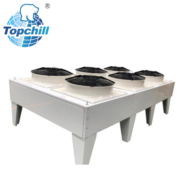
Specifying an air-cooled system over water-cooled or evaporative condensing solutions depends on technical thresholds. Air-cooled units eliminate water consumption and the associated chemical treatment programs. You must evaluate footprint considerations, water scarcity regulations, and maintenance overhead associated with each configuration. Air-cooled configurations require specific airflow dynamics in dense industrial layouts. They need adequate clearance to prevent recirculating hot discharge air back into the intake. A refrigeration heat rejection system must breathe freely to maintain efficiency.
When comparing a TP Condenser to evaporative alternatives, consider the following operational differences:
Comparing fixed-speed AC motors with Variable Speed Drive (VSD) and Electronically Commutated (EC) motors reveals significant differences in part-load efficiency and head pressure control. EC motors modulate speed seamlessly, maintaining stable pressures while reducing energy consumption during cooler weather. Assess the structural and performance differences between induced draft and forced draft fan designs. Induced draft pulls air through the coil, providing even air distribution. Forced draft pushes air, which can be useful in specific spatial constraints. Fan blade design directly impacts acoustic output and volumetric airflow, requiring careful selection for noise-sensitive sites.
Traditional copper tube/aluminum fin construction offers proven reliability. Microchannel heat exchanger (MCHE) designs provide lower weight and significant refrigerant charge reduction. However, MCHE coils require precise filtration to prevent clogging. Factory-applied protective coatings, such as e-coating, epoxy, or phenolic treatments, mitigate galvanic corrosion in coastal or chemically aggressive industrial environments. The relationship between fin spacing (FPI - Fins Per Inch) and fouling rates is critical. Wide fin spacing prevents rapid clogging in dusty or debris-heavy locations. A TP air cooled condenser operating in a paper mill requires vastly different fin spacing than one on a clean commercial rooftop.
| Coating Type | Application Method | Corrosion Resistance Level | Best Use Case |
|---|---|---|---|
| Polyurethane | Spray applied | Moderate | General urban environments with mild pollution. |
| Epoxy Electrocoat (E-Coat) | Immersion bath | High | Coastal areas with high salt spray exposure. |
| Phenolic | Dip and bake | Extreme | Chemical plants and highly corrosive industrial sites. |
Design requirements differ for current HFC/HFO blends versus transitioning to natural refrigerants like CO2, Ammonia, or Propane. Evaluate pressure ratings, burst pressure thresholds, and material compatibility required for high-pressure refrigerants like R-744 (CO2). Address compliance with updated EPA/AIM Act mandates and global phase-down schedules. Selecting a unit compatible with low-GWP refrigerants protects your investment against future regulatory bans.
Accessible pressure monitoring ports (Schrader valves) and heavy-duty gauges are essential for routine system pressure checks. Built-in liquid line sight glasses and electronic refrigerant level sensors detect low-charge conditions before they cause compressor overworking. Assess ease of coil maintenance. Access panels must allow for high-pressure washing without damaging delicate fin structures. Proper maintenance access ensures the unit operates at peak efficiency throughout its lifespan.
Routine serviceability checks should include:
Staging fans or modulating fan speeds maintains stable condensing pressures during variable ambient conditions. Evaluate the integration capabilities of the condenser’s control panel with modern Building Management Systems (BMS) and supervisory refrigeration controls. Implement floating head pressure control for optimized energy consumption during low-ambient periods. This strategy allows condensing pressures to drop with ambient temperatures, significantly reducing compressor energy usage.
Undersizing a condenser to reduce initial purchase costs results in a long-term energy penalty and accelerated compressor wear. The financial impact of maintenance frequency, coil cleaning accessibility, and the cost of unplanned downtime far outweighs minor savings on capital expenditure. Calculate the payback period of premium features like EC motors and advanced coil coatings. These features reduce operating costs and extend equipment life, providing a strong return on investment.
Examine the trade-off between physical size constraints, such as roof load limits and pad sizes, and the necessity for larger heat transfer surface areas to achieve lower condensing temperatures. Larger coils reject heat more efficiently but require more space and structural support. Discuss the balance between acoustic limitations, which require low-velocity fans, and the need for high-velocity airflow to maximize heat rejection in compact footprints. You must balance noise restrictions with performance requirements.
Strict clearance requirements and site placement best practices ensure unobstructed intake and exhaust. Installing units in architectural wells, near high walls, or adjacent to other heat-rejecting equipment risks airflow short-circuiting, where hot exhaust air is drawn back into the intake. Mitigate prevailing wind impacts on fan performance and head pressure stability by orienting the unit correctly or installing wind baffles. Proper placement is as important as proper sizing.
Engineering standards dictate sizing discharge gas lines to maintain adequate refrigerant velocity without inducing excessive pressure drop. Poor oil return during low ambient operation and part-load conditions damages compressors. Specify the requirements for discharge line traps, inverted traps, and proper piping pitch to protect the compressor. Correct piping design ensures oil travels through the system and returns safely to the compressor crankcase.
Swapping an older unit for a modern condenser presents compatibility issues, such as matching mismatched legacy piping diameters. Establish system flushing protocols to mitigate oil contamination issues when transitioning from mineral oil to POE oil. Address structural load verification guidelines when replacing bulkier copper/aluminum units with lighter microchannel technology on legacy roof structures. Ensure the existing structure can support the new equipment configuration.
A: Industrial condensers are built for continuous, heavy-duty operation. They feature thicker coil materials, advanced corrosion protection, and higher capacity ratings. This allows them to handle larger heat loads and survive in harsher environments compared to standard commercial units.
A: Calculate THR by adding the net refrigeration cooling capacity to the heat generated by the compressor motor and the suction line superheat. You must apply specific heat multipliers based on whether the compressor is open, semi-hermetic, or hermetic.
A: Match components by plotting the compressor performance curves against the condenser capacity at your specific design ambient temperatures. Ensure the condenser can reject the required heat at the target condensing temperature without causing pressure imbalances or liquid floodback.
A: Yes. When equipped with proper capacity control mechanisms like variable speed EC motors, fan staging, or floating head pressure controls, air-cooled units maintain stable operation and prevent liquid floodback during extreme low ambient conditions.
A: Fin spacing determines how easily the coil clogs with airborne debris. Wider spacing, or a lower Fins Per Inch (FPI) count, is necessary in dusty or industrial environments to prevent rapid fouling, maintain proper airflow, and allow for easier high-pressure cleaning.


