Views: 0 Author: Site Editor Publish Time: 2026-07-26 Origin: Site


Airflow restrictions kill cooling performance by stopping heat rejection from the refrigerant to the ambient environment. When airflow hits a wall—whether from structural obstructions, mechanical failures, or environmental debris—the system faces high head pressure, spiked energy consumption, and lost cooling capacity. Finding and fixing these bottlenecks keeps heat transfer rates where they belong and prevents compressor failure.
Heat rejection drives any mechanical cooling system. Without enough air volume moving across the coil fins, the thermodynamic cycle stalls. Knowing exactly what causes these restrictions lets technicians and facility managers apply direct fixes. You will learn how to spot structural roadblocks, diagnose thermodynamic symptoms like hot air recirculation, and use field-tested engineering strategies to get system efficiency back on track. We will look at the physical mechanics of air movement, the environmental factors that block it, and the diagnostic tools needed to measure the exact impact of restricted airflow on the refrigeration cycle.
An air cooled condenser depends entirely on constant air velocity and mass flow rate to push heat from the high-pressure refrigerant into the surrounding air. As hot discharge gas enters the coil, the fan forces cooler ambient air across the finned surface. This forced convection drives the phase change of the refrigerant from a superheated vapor into a subcooled liquid. Any drop in air volume directly cuts the amount of heat the system can reject. The condensation process slows down, leaving the refrigerant too hot as it heads toward the metering device.
The relationship between air volume and heat transfer is linear up to a point. If you cut the airflow in half, you drastically reduce the coil's ability to shed BTUs. In the field, this means the compressor runs longer, works harder, and generates more internal heat. The physics dictate that heat moves from a warmer substance to a cooler one. If the air moving across the coil is moving too slowly, it absorbs heat, becomes hot itself, and stays in contact with the coil too long, eliminating the temperature difference needed for further heat transfer.
Air performance comes down to the fan and coil assembly moving a specific volume of air against resistance. Pressure drop happens when air hits friction passing through the coil fins, louvers, or fan guards. High pressure drop means high resistance, which kills overall air velocity. To beat this resistance, the fan motor works harder. If the static pressure goes past the fan's design limits, airflow drops off a cliff, and the coil fails to handle the thermal load.
Technicians measure this performance in cubic feet per minute (CFM) and static pressure (inches of water column). A standard axial fan blade is designed to move a high volume of air at a relatively low static pressure. When debris or physical barriers increase that pressure, the axial fan loses its grip on the air, causing turbulence and backflow. The air simply churns around the fan blade instead of pulling straight through the coil, rendering the fan highly inefficient.
Small drops in static pressure look harmless at first, but they stack up into heavy operational penalties. A restricted coil makes the compressor pump against higher discharge pressures, driving up the compression ratio. This cuts the system's Coefficient of Performance (COP) and spikes electrical energy consumption. Running under these strained conditions accelerates mechanical wear and tears years off the equipment's lifespan.
Consider the electrical impact. A compressor drawing 15 amps under normal conditions might draw 22 amps when fighting a restricted coil. That extra amperage translates directly into higher utility bills and massive heat generation within the compressor motor windings. Over a single cooling season, a 10% restriction in airflow can increase operating costs by 15% to 20%, while simultaneously degrading the lubricating properties of the compressor oil due to excessive heat.
Landscaping causes massive airflow problems. Shrubs, tall weeds, and low-hanging branches physically block the intake zones of outdoor units. When vegetation grows tight against the coil face, it ruins the uniform distribution of air, making the fan pull air from a smaller surface area. Keeping strict minimum clearance guidelines—usually 18 to 24 inches of dead space around the perimeter—keeps the volumetric airflow where it needs to be.
In commercial settings, landscaping crews often plant decorative bushes right up against ground-level units to hide them from public view. As these bushes mature, their root systems and branches form a solid wall. The unit ends up pulling in dead leaves, dirt, and moisture, which rots the aluminum fins and clogs the microchannels. Regular trimming and establishing a gravel or concrete perimeter around the unit is mandatory for long-term reliability.
Aesthetics fight mechanical requirements constantly. Property managers often install aftermarket decorative covers or privacy screens to hide equipment, completely ignoring airflow needs.
Decorative covers choke air intake by slashing the free-area percentage available for airflow.
Privacy fences built inches from the unit create a hard barrier that spikes static pressure.
Micro-mesh screens, meant to block debris, trap cottonwood, dust, and pollen, building a solid mat over the coil.
Custom brick enclosures trap heat and force the unit to rebreathe its own exhaust air.
When an enclosure is necessary, it must be designed with louvered panels that offer at least 70% free area. Solid wood fences or tight lattice work will destroy a compressor in a matter of months. The air needs a clear, straight path into the coil and an unobstructed path out the top.
Space limits dictate how well a unit breathes. A compact air cooled condenser installed in zero-lot-line residential setups or tight mechanical rooms takes a beating from bad clearance. When units get shoved into corners or against solid masonry walls, the fan starves for ambient air. Sticking to 360-degree clearance rules stops negative pressure zones and keeps the coil working within its design limits.
In urban environments, units are often placed in narrow alleys between buildings. These alleys act like wind tunnels or dead air traps, depending on the prevailing winds. If the unit is too close to the wall, the air velocity entering the coil is uneven. The side facing the wall pulls almost no air, while the outward-facing side does all the work. This uneven loading causes uneven refrigerant condensing, leading to erratic expansion valve operation indoors.
The physical orientation of the equipment against environmental factors changes everything. Bad installation of a vertical air cooled condenser near prevailing wind barriers, solid overhangs, or parapet walls builds dead air zones. If the discharge air hits a barrier, it creates turbulence that breaks the upward exhaust plume, crippling the unit's ability to dump heat.
Wind direction matters. If a unit is installed so that prevailing winter winds blow directly into the discharge fan, the fan motor will struggle to maintain RPM, and the head pressure will fluctuate wildly. Proper positioning requires analyzing the site's wind patterns, roof structures, and adjacent buildings to ensure the exhaust air can escape into the atmosphere without being pushed back down into the coil.
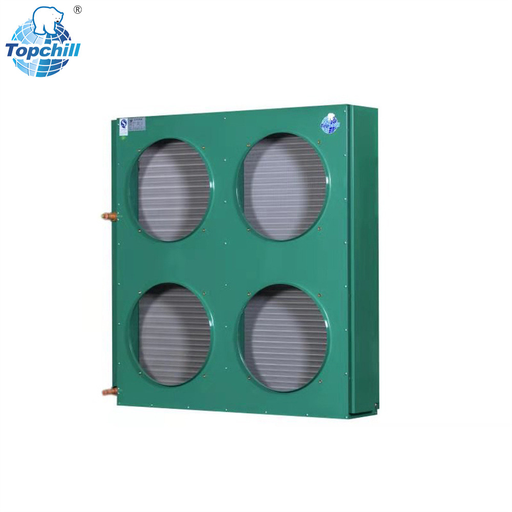
Environmental debris works like a thermal blanket. Dirt, pet hair, grass clippings, and mineral scaling pack deep inside the microchannel or tube-and-fin structures. This fouling physically plugs the air paths and insulates the copper or aluminum surfaces, stopping heat from moving to the air stream. Even a thin layer of grime wrecks the effective heat transfer coefficient of the coil.
Cottonwood seeds are particularly destructive. They float through the air and stick to the slightly damp, warm surface of the coil, weaving themselves into a tight, felt-like blanket. Once this blanket forms, static pressure skyrockets. The fan continues to spin, but no air moves through the fins. The only fix is physically peeling the mat off and chemically washing the remaining debris out of the fin pack.
Airflow restrictions are not just external; internal mechanical wear drops air velocity fast.
Fan motor bearings wear out, dropping RPMs and lowering the total cubic feet per minute (CFM).
Installing a replacement fan blade with the wrong pitch changes the airflow profile completely.
Weak run capacitors make the fan motor run slow, overheat, and eventually drop out on thermal overload.
Slipping belts in belt-driven commercial fan assemblies cause erratic, weak fan rotation.
Missing fan shrouds or broken baffles allow air to bypass the coil entirely.
Technicians must verify fan motor amperage and RPM during every maintenance visit. A motor drawing high amps is likely failing or fighting high static pressure. Replacing a fan blade requires matching the exact diameter, pitch, and hub location of the OEM blade. A blade sitting too high or too low in the shroud will not move the correct volume of air, regardless of motor RPM.
In specialized commercial setups, the air path runs through ductwork. Fire dampers and control dampers inside these ducts restrict airflow if they fail to open fully or get stuck. Also, flexible duct runs connected to a remote refrigeration condenser sag over time. Water pooling inside these sagging flex ducts builds severe physical blockages, choking the air supply and sending head pressures through the roof.
Rigid ductwork is always preferred for moving air to and from remote units. If flex duct must be used, it needs to be pulled tight and supported every few feet with wide saddles to prevent sagging. Any sharp bends or kinks in the ductwork will add massive static pressure to the system, requiring a larger, more powerful blower motor to overcome the resistance.
Hot Air Recirculation happens when the hot discharge air blowing out the top of the unit gets sucked back into the intake louvers. This short-circuiting hits hard in confined spaces, under low overhangs, or when multiple units sit too close together. HAR artificially drives up the entering air dry-bulb temperature. Since the ambient air is already hot, the temperature difference between the air and the refrigerant shrinks, killing heat exchange efficiency.
Imagine a unit designed to operate in 95-degree ambient air. If HAR occurs, the air entering the coil might be 115 degrees. The system is now trying to reject heat into air that is already hotter than the condensing temperature of the refrigerant. The compressor will run continuously, head pressure will trip the high-pressure safety switch, and the building will lose cooling entirely. Fixing HAR often requires installing discharge air hoods or physically relocating the equipment.
Blocking airflow triggers an immediate, violent rise in head pressure. Because the heat cannot escape, the refrigerant stays in a high-pressure vapor state longer. This sparks a common field debate regarding subcooling. When airflow is restricted, subcooling readings actually go up. This happens because the head pressure climbs much faster than the liquid line temperature can normalize, creating a higher calculated subcooling value even though the system is failing.
Technicians often misdiagnose this high subcooling as an overcharge. They recover refrigerant to bring the subcooling down, which starves the evaporator coil and drops the suction pressure. The real problem was never the charge; it was the lack of airflow across the outdoor coil. Always verify airflow and coil cleanliness before connecting gauges or adjusting the refrigerant charge.
Running with restricted airflow forces the compressor to take extreme thermal abuse. High discharge temperatures cook the refrigeration oil, causing acid formation and sludge buildup. This thermal overload eventually burns through the compressor stator windings, causing a dead short to ground. Also, failing to condense the refrigerant properly leaves the evaporator coil starved, causing a massive drop in sensible and latent cooling capacity indoors.
The compressor relies on cool suction gas returning from the evaporator to cool its internal motor windings. When the outdoor coil is restricted, the liquid refrigerant entering the metering device is too hot. It flashes off too quickly in the evaporator, providing very little cooling effect. The suction gas returning to the compressor is therefore too warm to cool the motor, leading to a rapid, catastrophic failure of the compressor mechanics.
The first step in finding airflow issues is a hard visual inspection. Technicians need to look for flattened fins caused by hail damage, aggressive pressure washing, or physical impact. Shining a flashlight through the coil face exposes deep-seated clogs, like matted pollen or pet hair, that hide from a quick glance.
Look at the ground around the unit. If there is a heavy buildup of dryer lint, grass clippings, or leaves, that debris is likely inside the coil as well. Inspect the fan blade for cracks or missing balancing weights. A vibrating fan motor indicates an out-of-balance blade, which reduces RPM and airflow. Check the fan shroud for proper alignment; the blade should sit exactly where the manufacturer specifies to maximize air draw.
Refrigeration gauges give the thermodynamic proof of an airflow restriction. The classic symptom is abnormally high head pressure paired with elevated liquid line temperatures. By measuring actual subcooling and superheat accurately, technicians isolate airflow issues from other mechanical problems, like a system overcharge or a hunting thermostatic expansion valve (TXV).
If the head pressure is high, the subcooling is high, and the superheat is normal to slightly high, you have an airflow problem on the high side. Connect temperature probes to the liquid line and the suction line. Use digital gauges to get precise saturation temperatures. The data will clearly show that the refrigerant is not rejecting heat, pointing directly to a dirty coil, a failing fan motor, or a physical blockage.
Measuring the temperature delta (TD) across the coil paints a clear picture of heat rejection. A restricted coil usually shows an abnormally high temperature split because the tiny volume of air moving through the fins absorbs way too much heat. Technicians also use anemometers to measure the actual air velocity (CFM) blowing out the top of the fan shroud, comparing these numbers against the manufacturer's baseline specs.
Diagnostic Method | Symptom of Restriction | Field Implication |
|---|---|---|
Visual Inspection | Flattened fins, heavy dirt matting | Physical blockage preventing air entry |
Gauge Readings | High head pressure, high subcooling | Inability to reject heat efficiently |
Temperature Delta (TD) | Abnormally high temperature split | Low air volume absorbing too much heat |
Anemometer Test | Low CFM at discharge shroud | Fan underperforming or severe static resistance |
Amp Draw Test | High compressor amps, low fan amps | Compressor straining, fan moving no air mass |
Getting airflow back requires strict maintenance habits. Chemical coil washing procedures need careful selection; alkaline cleaners work best for standard grease and dirt, while acidic cleaners handle severe oxidation. Technicians must use proper fin combing tools to straighten bent aluminum fins, opening up the original geometric pathways needed for full air velocity.
When washing a coil, always wash from the inside out. Pushing water from the outside in just drives the dirt deeper into the fin pack. Remove the top of the unit, pull the fan motor aside, and use a low-pressure water stream to flush the debris back out the way it came in. Apply the chemical cleaner, let it dwell for the manufacturer's recommended time, and rinse thoroughly until the water runs completely clear.
Picking the right equipment architecture stops airflow issues before they begin. Choosing a vertical discharge unit pushes hot exhaust air straight up, away from walkways and adjacent walls. Using a remote configuration lets engineers move the heat rejection process to a rooftop or open area with massive ambient airflow. When space is tight, installing a compact unit built with high-static fans guarantees the system can push through tight architectural footprints.
Engineers must calculate the total heat of rejection (THR) for the system and select a coil that can handle that load at the specific ambient design temperature of the location. Oversizing the coil slightly can provide a buffer against future fouling, but it requires careful management of the refrigerant charge and head pressure controls during low ambient conditions.
Architectural enclosures must respect thermodynamics. When building protective louvers, wind baffles, or security cages, contractors have to calculate the free-area percentage to ensure it meets or beats the manufacturer's airflow requirements. Proper louver angling and wide spacing stop the creation of high static pressure zones, letting the Condenser breathe without restriction.
If a security cage is required to prevent theft or vandalism, use heavy-gauge wire mesh with large openings rather than expanded metal. Expanded metal acts like a cheese grater, slicing the air and creating massive turbulence. The goal is to protect the equipment without changing the aerodynamic profile of the air entering the coil.
Enforce a strict clearance zone of at least 24 inches around all outdoor units to guarantee unrestricted air intake.
Schedule routine visual inspections and chemical cleanings to flush out deep-seated debris before it spikes static pressure.
Evaluate all architectural screens, fences, or decorative covers for adequate free-area airflow, and remove them if they cause hot air recirculation.
Measure temperature splits and fan motor amp draws during every service call to catch mechanical airflow restrictions early.
A: Shrubs and vegetation must be planted at least 18 to 24 inches away from the exterior panels. This clearance ensures the fan can draw sufficient ambient air without creating negative pressure zones or pulling leaves into the coil fins.
A: A dirty coil acts as an insulator and restricts airflow, forcing the compressor to work harder to reject heat. This increases the discharge pressure and compression ratio, which directly causes the system to draw more electrical current.
A: Using a high-pressure washer is highly discouraged. The intense water pressure easily bends and flattens the delicate aluminum fins, which permanently restricts airflow and destroys the coil's heat transfer capabilities.
A: Hot air recirculation happens when the heated exhaust air from the top of the unit is pulled back into the side intake louvers. This raises the entering air temperature, drastically lowering the system's cooling capacity.
A: When airflow is blocked, the heat cannot escape, causing the head pressure to spike rapidly. Because the pressure rises much faster than the liquid line temperature can adjust, the calculated subcooling value artificially increases.
A: Most decorative covers are not safe during operation because they significantly reduce the free-area available for air intake. They create high static pressure and often lead to compressor overheating and premature failure.


